
Operating instructions


6 Cisco Systems Intelligent Gigabit Ethernet Switch Module
2.1 IBM eServer BladeCenter architecture
In this section, we look into the architectural design of the BladeCenter chassis and
components.
2.1.1 The midplane
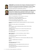
In Figure 2-2, we discuss the BladeCenter midplane. The midplane has two similar sections
(upper and lower) that provide redundant functionality. The processor blades (blade servers)
plug into the front of the midplane. All other major components plug into the rear of the
midplane.
The processor blades have two connectors, one connected to the upper section and one to
the lower section of the midplane. All other components plug into one section only (upper or
lower). However, there will be another matching component that can plug into the other
midplane section for redundancy.
Figure 2-2 Midplane view
2.1.2 Management Module Ethernet
Discussed in Figure 2-3 on page 7 is the Management Module interface. The switch modules
are configured by the active Management Module through the use of a 100 Mb Ethernet
interface. Each Management Module has four 100 Mb Ethernet interfaces, one for each
switch module. Each switch module has two 100 Mb Ethernet interfaces, one for each
Management Module. The following list clarifies the routing:
Management Module 1 Ethernet 1
→ Switch Module 1 Ethernet 15
Management Module 1 Ethernet 2
→ Switch Module 2 Ethernet 15
IBM
^
BladeCenter™ - Midplane
Management
Module 1
Switch
Module
CPU
Blade
1
CPU
Blade
2
CPU
Blade
14
Blower
Blower
Power
Module
Power
Module
Power
Module
Power
Module
Front
Panel/Media
Tray
Midplane Upper Section
Midplane Lower Section
Management
Module 2
Switch
Module
Switch
Module
Switch
Module