
Operating instructions


162 Cisco Systems Intelligent Gigabit Ethernet Switch Module
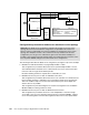
Figure 7-17 Desired RSPAN data flow for this example
Configurations presented for blade server attachment to this topology
The following list describes the blade server configuration (see Figure 7-18) for this example:
BladeServer1: 802.1Q trunk links carrying multiple VLANs to a NIC.
This configuration is provided to demonstrate how to permit multiple VLANs to access
each individual NIC in the blade server. It demonstrates one way to isolate traffic types
from each other, through several VLANs per NIC.
Broadcom teaming software is required, but no redundancy is used.
BladeServer2: Access ports to NICs via individual connections.
This configuration is provided to demonstrate how to use each NIC as a standard access
link (no VLANs, trunking, or redundancy are used from the blade server’s perspective).
This is the traditional way most servers were attached in the past and is simple and
effective, but not very flexible.
This configuration is performed using the stock network configuration tools available in
Windows 2000 (no teaming software is used).
BladeServer3: Access ports to NICs via SLB/teamed connections.
This configuration is provided to show how to use multiple NICs to look like a single
access NIC to the rest of the upstream network (the Cisco Systems IGESMs). It makes
use of the teaming drivers to tie the NICs together but does not use any special VLAN
Important: The blade server configurations offered in this chapter are not part of the
topology discussion, but instead their configurations are provided in this section as a
means to help you understand some of the possibilities for attaching the servers to this
topology. The examples should
not be construed as the way a blade server must be
configured. If your only goal is to understand a given server attachment example, it is
possible to just review that specific example and its associated upstream connection on the
Cisco Systems IGESMs and ignore the extra blade server configurations.
g2/25 Data Center 6500-1
g2/26
g2/2
g0/17
g0/18
g0/19 - Reflector-port
g0/1
CIGESM1
1
Blade
Server
1
BladeCenter
Sniffer
RSPAN source: Port g0/1 on
CIGESM1
RSPAN Reflector-port: Port g0/19 on CIGESM1
RSPAN VLAN: VLAN 500
RSPAN destination: Port g2/2 on 6500-1
VLAN500