
Operating instructions


Chapter 7. Cisco Systems IGESM configuration and network integration 157
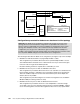
Figure 7-15 Windows 2000 networking showing only physical interfaces on BladeServer3
Figure 7-16 Windows 2000 networking showing only physical interfaces on BladeServer4
From the CMD prompt (Start → Run → cmd → OK), execute the ipconfig command and
confirm that the desired interfaces have the desired IP configuration on each blade server
(make sure that they are not reversed, where the IP address you want on the
Local Area
Connection
is not on the connection named Local Area Connection 2, assuming they have
not been renamed). For teamed interfaces, make sure that the IP address is on the expected
logical interface as reported by ipconfig.
Perform ping tests from the various boxes.
The following tests connectivity between blade servers on the same VLANs. Pings will only
travel up to the appropriate Cisco Systems IGESM and back to the other blade server (they
will not travel up to the aggregation switches).
Ping from BladeServer1 to 10.1.10.2 (BladeServer2’s VLAN 10 connection)
Ping from BladeServer1 to 10.1.20.2 (BladeServer2’s VLAN 20 connection)
The following tests connectivity through the Cisco Systems IGESMs and up to the 6500s:
Ping from BladeServer1 to 10.1.10.254 (HSRP address on the 6500s)
Ping from BladeServer1 to 10.1.15.254 (HSRP address on the 6500s)
Ping from BladeServer1 to 10.1.20.254 (HSRP address on the 6500s)
Ping from BladeServer1 to 10.1.25.254 (HSRP address on the 6500s)
Ping from BladeServer2 to 10.1.10.254 (HSRP address on the 6500s)
Ping from BladeServer2 to 10.1.20.254 (HSRP address on the 6500s)
Ping from BladeServer3 to 10.1.30.254 (HSRP address on the 6500s)