
Operating instructions


Chapter 7. Cisco Systems IGESM configuration and network integration 143
On BladeServer1, both ports will be using trunking (but not load balancing) through the
Broadcom BASP software. The first port will be configured for VLANs 10 and 15, the
second port will be configured for VLANs 20 and 25.
On BladeServer2, both ports will be simple access links and will be placed on VLANs 10
and 20, respectively, through port settings on the Cisco Systems IGESMs.
On BladeServer3, both ports will be teamed through the Broadcom BASP software to
appear as a single logical link to the OS, using access VLAN 30 as configured at the Cisco
Systems IGESM’s ports to this server.
On BladeServer4, both ports will be teamed through the Broadcom BASP software to
appear as a single logical link to the OS and use 802.1Q trunking to support VLANs 35,
40, 45, and 50.
Step 3.1: Configuring the first Cisco Systems IGESM (CIGESM1)
Table 7-9 shows the step-by-step instructions used to configure CIGESM1, showing both CLI
and CMS commands.
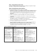
Table 7-9 Configuring CIGESM1
Important: The current version of CMS supported on the Cisco Systems IGESM has a
limitation in its ability to completely control VLANs being placed on a given trunk: It always
includes VLAN 1 and 1001-1005, even if you do not set them as allowed. Because of this
limitation, its use might not be appropriate for production configuration when trying to
control VLANs allowed on a given trunk.
Description and comments Actions via IOS CLI for CIGEMS1 Actions via CMS for CIGEMS1
Step 3.1.1:
Configure desired
VLANs for CIGESM1
.
Create VLANs 10, 15, 30, 35, 40,
45, and 50 (only named VLAN 10
and 15 for this demonstration).
Perform the following from the enable
mode:
config t
vlan 10
name Web
vlan 15
name User
vlan 30,35,40,45,50
Note that there are
no spaces between
the VLAN numbers and the commas.
Perform the following from the CMS
interface:
1. In the top menu bar, click VLAN →
VLAN.
2. Click the Configure VLANs tab.
3. Click Create.
4. Enter 10 in the VLAN ID field.
5. Enter Web in the VLAN Name field.
6. Click OK.
7. Click Create.
8. Enter 15 in the VLAN ID field.
9. Enter User in the VLAN Name field.
10. Click OK.
11. Click Create.
12. Enter 30 in the VLAN ID field (leave
the name field defaulted).
13. Click OK.
14. Repeat the previous three steps to
create VLANs 35, 40, 45, and 50.
15. Click Apply.
16. Click Refresh to view the newly
created VLANs.