
Operating instructions


Chapter 7. Cisco Systems IGESM configuration and network integration 137
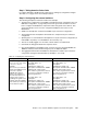
Run the command show etherchannel 1 port-channel and check for the desired output
(it should be
similar on both Cisco Systems IGESMs):
Port-channels in the group:
----------------------
Port-channel: Po1 (Primary Aggregator)
------------
Age of the Port-channel = 01d:05h:15m:50s
Logical slot/port = 1/0 Number of ports = 4
HotStandBy port = null
Port state = Port-channel Ag-Inuse
Protocol = LACP
Ports in the Port-channel:
Index Load Port EC state No of bits
------+------+------+------------------+-----------
0 00 Gi0/17 Active 0
0 00 Gi0/18 Active 0
0 00 Gi0/19 Active 0
0 00 Gi0/20 Active 0
Check the output of the show cdp neighbors command. It should show something similar
to the following (different Device IDs for the CIGESM2). Note that the Cisco Systems
IGESMs can see each other through the Management Module interface.
Capability Codes: R - Router, T - Trans Bridge, B - Source Route Bridge
S - Switch, H - Host, I - IGMP, r - Repeater, P - Phone
Device ID Local Intrfce Holdtme Capability Platform PortID
DC6500-1 Gig 0/20 179 R S I WS-C6506 Gig 2/28
DC6500-1 Gig 0/19 179 R S I WS-C6506 Gig 2/27
DC6500-1 Gig 0/18 179 R S I WS-C6506 Gig 2/26
DC6500-1 Gig 0/17 179 R S I WS-C6506 Gig 2/25
CIGESM2 Gig 0/15 141 S I OS-CIGESM-Gig 0/15
Verifying correct operation on the external switches (6500-1 and 6500-3)
The following section includes some commands you can use to verify the desired
configuration and operation of the 6500s.
You can run the same set of commands as previously shown for the Cisco Systems IGESMs.
Naturally, there will be some differences in the output, but you want to make sure that the
proper ports are channeled and trunked and carrying the correct VLANs. Also watch out for
any admin down ports. You should also be able to ping the following addresses:
Ping to BladeServer1 at 10.1.10.1
Ping to BladeServer1 at 10.1.15.1
Ping to BladeServer1 at 10.1.20.1
Ping to BladeServer1 at 10.1.25.1
Ping to BladeServer2 at 10.1.10.2
Ping to BladeServer2 at 10.1.20.2
7.5.2 Topology 2: Dual Cisco Systems IGESMs, two-port aggregation to two 6500s
In this example (reference Figure 7-8), uplinks from the BladeCenter are divided between two
aggregation switches. This topology is a more traditional high availability configuration, in that
the loss of one of the aggregation switches or channeled links will now
not result in lost traffic,
regardless of NIC Teaming/Trunk Failover configuration. The BladeCenter Cisco Systems
IGESMs will be participating in Spanning Tree, with the EtherChannel ports 19 and 20 on
both Cisco Systems IGESMs going into blocking (assuming 6500-1 is the root of the
Spanning Tree).