
Operating instructions


Chapter 7. Cisco Systems IGESM configuration and network integration 127
Step 3: Configuring Cisco Systems IGESMs
This section steps through the sequence of actions required to configure the Cisco Systems
IGESMs for this example. It has two major sections: one for configuring the Cisco Systems
IGESM in bay 1 and one for configuring the Cisco Systems IGESM in bay 2.
The following assumptions have been made for both Cisco Systems IGESM configurations in
this example:
The user is already logged on to the Cisco Systems IGESM and the switch is in enable
mode (or logged into CMS and using the GUI therein).
Commands are being performed in the sequence shown.
The Cisco Systems IGESM is starting from a base configuration per the “Cisco Systems
IGESM base configurations” on page 108.
The operating systems in use on the blade servers are Windows 2000. This is important,
because which port is considered “first” and which port is considered “second” on a blade
server has several dependences, not the least of which is the operating system in use. For
an explanation of the blade servers’ connection names and how they are derived, see
Appendix A, “Hints and tips” on page 227.
On BladeServer1, both ports will be using trunking (but not load balancing) through the
Broadcom BASP software. The first port will be configured for VLANs 10 and 15; the
second port will be configured for VLANs 20 and 25.
On BladeServer2, both ports will be simple access links and will be placed on VLANs 10
and 20, respectively, through port settings on the Cisco Systems IGESMs.
Step 3.1: Configuring the first Cisco Systems IGESM (CIGESM1)
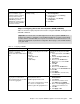
Table 7-4 shows the steps in configuring CIGESM1, showing both CLI and CMS commands.
Table 7-4 Configuring CIGESM1
Important: The current version of CMS supported on the Cisco Systems IGESM has a
limitation in its ability to completely control VLANs being placed on a given trunk: It always
includes VLAN 1 and 1001-1005, even if you do not set them as allowed. Therefore, its use
might not be appropriate for production configuration when trying to control VLANs allowed
on a given trunk.
Description and comments Actions via IOS CLI for CIGEMS1 Actions via CMS for CIGEMS1
Step 3.1.1:
Configure desired
VLANs for CIGESM1
.
Create and name VLANs 10
and 15.
Perform from the enable mode:
config t
vlan 10
name Web
vlan 15
name User
In the CMS interface:
1. On the top toolbar, click VLAN → VLAN.
2. Click the Configure VLANs tab.
3. Click Create.
4. Enter 10 in the VLAN ID field.
5. Enter Web in the VLAN Name field.
6. Click OK.
7. Click Create.
8. Enter 25 in the VLAN ID field.
9. Enter User in the VLAN Name field.
10. Click OK.
11. Click Apply.
12. Click Refresh to view the new VLANs.