
Operating instructions


126 Cisco Systems Intelligent Gigabit Ethernet Switch Module
Step 1: Taking down the link or links
You should disable links before making any configuration changes (Table 7-1 on page 122).
Step 2: Configuring the external switches
The following assumptions have been made for this example:
The bulk of the configuration for the 6500s is included in the base configuration (see “Cat
6500 base configurations” on page 109), because the goal of this document is to show
how to configure the BladeCenter components rather than generic Cisco devices. This
section specifically focuses on configuring the 6500 ports that connect to the BladeCenter.
VLAN 2 has already been created on the 6500s as part of the base configuration.
VTP Domain has already been named and set to transparent as part of the base
configuration.
Spanning Tree root commands have already been set as part of the base configuration (to
make 6500-1 the primary root and 6500-3 the secondary root).
The user is already logged on to the switch, and the switch is in enable mode.
Commands are being performed in the sequence shown.
Cisco Switch Modules in the 6500s being used to connect to the Cisco Systems IGESMs
are 1000Base-T-based, and we will be leaving the ports at 1 Gbps full duplex.
The aggregation link between the 6500s has already been created as part of the base
config and is carrying the desired VLANs (for example, 2, 10, 15, 20).
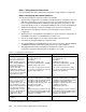
Table 7-3 Configuring the external switches
Description and comments On the 6500-1 On the 6500-3
Step 2.1: Create link
aggregation
. This is for the
port-channel between the
6500s and their respective
Cisco Systems IGESMs. It is
always a good practice to
provide a description to an
interface. Note that
spanning-tree guard root is
added to both the individual
ports and the port-channel to
ensure that it is in place.
config t
int range g2/25 - 28
switchport
spanning-tree guard root
description To-BladeCenter CIGESM1
channel-group 2 mode active
This creates a logical interface named
Port-Channel2 and places the interfaces
g2/25 through g2/28 into it.
config t
int range g2/25 - 28
switchport
spanning-tree guard root
description To-BladeCenter CIGESM2
channel-group 2 mode active
This creates a logical interface named
Port-Channel2 and places the interfaces
g2/25 through g2/28 into it.
Step 2.2:
Configure VLAN
and trunking options on the
newly created port channels
.
All desired VLANs were
already created as part of the
base configuration, and IP
addresses were added at that
time. This step sets up the
aggregated links created in
step 2.1 to be 802.1Q trunks
and allows the desired
VLANs to be carried.
int port-channel 2
description EtherChannel to CIGESM1
switchport trunk encapsulation dot1q
switchport trunk native vlan 2
switchport trunk allowed vlan 2,10,15
switchport mode trunk
spanning-tree guard root
end
Note: Configuring root guard on the port
channel interface between 6500-1 and the
Cisco Systems IGESM will help to ensure
stability in your network.
int port-channel 2
description EtherChannel to CIGESM2
switchport trunk encapsulation dot1q
switchport trunk native vlan 2
switchport trunk allowed vlan 2,20,25
switchport mode trunk
spanning-tree guard root
end
Note: Configuring root guard on the port
channel interface between 6500-3 and the
Cisco Systems IGESM will help to ensure
stability in your network.
Step 2.3:
Save config to
NVRAM
.
a
a. Failure to save your configuration results in possible network-down conditions if the switch is restarted prior to
the save. (All changes since last save will be lost.)
copy running-config startup-config copy running-config startup-config