
Operating instructions


Chapter 7. Cisco Systems IGESM configuration and network integration 125
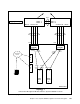
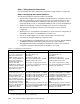
Figure 7-3 Topology 1
17 18 19 20
CIGESM1
Data Center 6500-1
Mod 6 - 1
Mod 6 - 2
Mod 2 - 25 26 27 28
Data Center 6500-3
Mod 6 - 1
Mod 6 - 2
25 26 27 28 - Mod 2
17 18 19 20
CIGESM2
1 2
Blade
Server
1
1 2
Blade
Server
2
M
M
1
M
M
2
Po1
Po2 Po2
Management
Netw or k
Management
Workstation
Po1Po1
To Core Routers
Aggregation Layer
BladeCenter
Topology 1
Links between Management Modules and CIGESMs not shown.
Trunked
VLAN 10
and 15
Trunked
VLAN 20
and 25
Access Access
Trunked
VLAN 10
and 15
Trunked
VLAN 20
and 25
Access
VLAN 10
Access
VLAN 20
Links between Management Module and Cisco Systems IGESMs not shown.