
Operating instructions


Chapter 7. Cisco Systems IGESM configuration and network integration 101
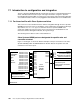
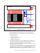
Figure 7-2 Overall view of port connections within a BladeCenter
Ports G0/1 through G0/14: Connects to blade server slots 1 through 14, respectively:
Preset default values for ports going to the blade servers (includes ports g0/1 through
g0/14, shown is for g0/1):
description blade1
switchport access vlan 2
switchport trunk native vlan 2
switchport trunk allowed vlan 2-4094
switchport mode trunk
spanning-tree portfast trunk
spanning-tree bpdufilter enable
Hard-coded to Auto negotiation, but only support 1000/full duplex to the blade servers.
This cannot be changed at this time, but future revisions of code may support the ability to
set these ports to a no negotiate condition and force the link to 1000/full.
Port defaults to operate as a trunk link (switchport mode trunk) carrying VLANs 2 through
4094 (switchport trunk allowed vlan 2-4094).
If no changes are made to these defaults (trunk port with native VLAN 2), when a server is
attached to this port with no special software —for example, the BASP teaming software
discussed later in this chapter—the server shows up as being on VLAN 2. To use a
different VLAN, either use BASP software to assign VLANs at the blade server or change
1
B
S
S
1
2
1
B
S
S
1
4
2
1
B
S
S
2
2
1
B
S
S
3
2
1
B
S
S
4
2
1
B
S
S
5
2
1
B
S
S
6
2
1
B
S
S
7
2
1
B
S
S
8
2
1
B
S
S
9
2
1
B
S
S
1
0
2
1
B
S
S
1
1
2
1
B
S
S
1
2
2
1
B
S
S
1
3
2
1 2 3 4 5 6 7 8 9 10 11 12 13 14 15 16 17
18
19
Bottom IGESM (Bay 2) 20
MM1
MM2
Top IGESM (Bay 1) 17
18
19
1 2 3 4 5 6 7 8 9 10 11 12 13 14 15 16 20
IGESM
External
uplinks
IGESM
External
uplinks
MM1
Uplink
MM2
Uplink
BladeCenter Chassis
Eth1
Eth1
Eth0
Eth0
(BSS = Blade Server Slot)