
Operation Manual


Chapter 4 Operation of Front Panel Indicators
38 TP-00100
Initial Power On, Calibration, and Registration (AC
Power applied)
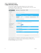
The following chart illustrates the sequence of steps and the corresponding
appearance of the Wireless Gateway front panel LED status indicators during power
up, calibration, and registration on the network when AC power is applied to the
Wireless Gateway. Use this chart to troubleshoot the power up, calibration, and
registration process of your Wireless Gateway.
Note: After the Wireless Gateway completes Step 7 (Data Network Registration
Complete), the Wireless Gateway proceeds immediately to Normal Operations. See
Normal Operations (AC Power applied) (on page 40).
Front Panel LED Status Indicators During Initial Power Up, Calibration, and
Registration
Part 1, High Speed Data Registration
Step: 1 2 3 4 5 6
Front Panel
Indicator
Self
Test
Downstream
Scan
Downstream
Signal Lock
Ranging
Requesting IP
Address
Request High
Speed Data
Provis ioning Fil e
1
POWER
On
On
On
On
On
On
2
US/DS
On
Blinking
On
On
On
On
3
ONLINE
On
Off
Off
Off
Off
Blinking
4
2.4 GHz
On
On or Blinking
On or Blinking
On or
Blinking
On or Blinking
On or Blinking
5
5 GHz
On
On or Blinking
On or Blinking
On or
Blinking
On or Blinking
On or Blinking
6
TEL
1
On
Off
Off
Off
Off
Off
7
TEL
2
On
Off
Off
Off
Off
Off
8
BATTERY
On – When battery is charged
Blinks – When battery charge is low
Off – When there is no battery in the unit