Doc. No. 78-1812-08 Fast Ethernet Interface Processor (FEIP) Installation and Configuration Product Numbers: CX-FEIP-1TX=, CX-FEIP-2TX=, CX-FEIP-1FX=, CX-FEIP-2FX= This configuration note is a standalone publication that provides instructions for installing and configuring the Fast Ethernet Interface Processor (FEIP) in all Cisco 7000 series routers and Cisco 7500 series routers. (For specific compatibility requirements, refer to the section “Software and Hardware Prerequisites,” on page 3.
Document Contents Document Contents This publication includes the following sections: • • • • • • • If You Need More Information Installation Prerequisites on page 3 What Is the FEIP?, page 14 FEIP Installation, page 20 Configuring the Fast Ethernet Interfaces* on page 27 Upgrading FEIP Microcode, page 36 Cisco Connection Online on page 39 If You Need More Information The Cisco IOS software running your router contains extensive features and functionality.
Installation Prerequisites • To view Cisco documentation or obtain general information about documentation, refer to the following sources: — Documentation CD-ROM. — Cisco Connection Online (CCO). (Refer to the section “Cisco Connection Online,” on page 39.) — Customer Service at 800 553-6387 or 408 526-7208. Customer Service hours are 5:00 a.m. to 6:00 p.m. Pacific time, Monday through Friday (excluding company holidays). You can also send e-mail to cs-rep@cisco.com.
Installation Prerequisites Each FEIP is a fixed configuration; therefore, individual port adapters are not available as spare parts and are not field-replaceable or removable. The entire FEIP assembly is treated as a field-replaceable unit (FRU). Do not attempt to remove an FEIP’s port adapter and replace it with another. Do not attempt to simultaneously operate 100BASE-TX and 100BASE-FX port adapters on the same FEIP.
Safety Guidelines • • Do not perform any action that creates a potential hazard or makes the equipment unsafe. Carefully examine your work area for possible hazards such as moist floors, ungrounded power extension cables, and missing safety grounds. Telephone Wiring Guidelines Use the following guidelines when working with any equipment that is connected to telephone wiring or to other network cabling: • • Never install telephone wiring during a lightning storm.
Installation Prerequisites Guidelines for Interface Processor Installation and Removal This section describes mechanical functions of system components, emphasizes the importance of following correct procedures to avoid unnecessary board failures, and is for background only; specific procedures follow in the section “FEIP Installation” on page 20. You can remove and replace interface processors while the system is operating; you do not need to notify the software or reset the system power.
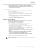
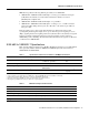
Guidelines for Interface Processor Installation and Removal Figure 1 Ejector Levers/Captive Installation Screws on the FEIP (Horizontal Orientation Shown) Interface processor card slot Ejector lever Interface processor card carrier guide (black) a b Captive installation screw H1984 c Note The FEIP is oriented horizontally in the Cisco 7010 and Cisco 7505 and vertically in the Cisco 7000, Cisco 7507, and Cisco 7513.
Installation Prerequisites Microcode Overview The FEIP microcode (firmware) is an image that provides card-specific software instructions. A programmable read-only memory (PROM) device on the FEIP contains a default microcode boot image that assists the system in finding and loading the microcode image from the Cisco IOS software bundle or Flash memory.
IEEE 802.3u 100BASE-T Specifications IEEE 802.
Installation Prerequisites What Is the Cisco 7000 Series? The Cisco 7000 series includes the Cisco 7000 and Cisco 7010 routers. The FEIP operates in the Cisco 7000 series routers. (For software and hardware requirements, refer to the section “Software and Hardware Prerequisites” on page 3.
What Is the Cisco 7500 Series? In the 5-slot Cisco 7010 (Figure 3), slots 0 through 2) are for interface processors including the FEIP. Figure 3 Cisco 7010 (Interface Processor End) RSP7000CI slot 4 RSP7000 slot 3 T E OL X.
Installation Prerequisites In the Cisco 7507 (see Figure 5), slots 0 and 1 and 4 through 6 are for interface processors including the FEIP.
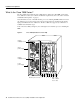
What Is the Cisco 7500 Series? In the Cisco 7513 (see Figure 6), slots 0 through 5 and 8 through 12 are for interface processors including the FEIP. Figure 6 Cisco 7513 (Interface Processor End) Blower module Cable-management bracket NO RM AL EN AB LE EJE CT SLO SLO T0 T1 SLA MAS VE TE R Card cage and processor modules SLA VE /M AS TE R CP U HA LT RE SE EN T AB LE AU X.
What Is the FEIP? What Is the FEIP? The FEIP provides up to two 100-Mbps, IEEE 802.3u Fast Ethernet interfaces. (Figure 7 shows a two-port 100BASE-TX FEIP.
FEIP LEDs Note Each FEIP is a fixed configuration; therefore, individual port adapters are not available as spare parts and are not field-replaceable or removable. The entire FEIP card is treated as a field-replaceable unit (FRU). Do not attempt to remove an FEIP’s port adapter and replace it with another. Do not attempt to install 100BASE-TX and 100BASE-FX port adapters on the same FEIP.
What Is the FEIP? Following are the three status LEDs and an explanation of what each indicates: • • MII—On when the MII port is selected as the active port by the controller. • RJ45 (or FIBER on FEIP-1FX or FEIP-2FX)—On when the RJ-45 (or FIBER) port is selected as the active port by the controller. Link—When the RJ-45 or SC port is active, this LED is on when the port adapter is receiving a carrier signal from the network.
FEIP Receptacles, Cables, and Pinouts The RJ-45 connection does not require an external transceiver. The MII connection requires an external physical sublayer (PHY) and an external transceiver. Figure 11 shows the RJ-45 cable connectors. RJ-45 cables are not available from Cisco Systems, but are available from commercial cable vendors. Table 3 lists the pinouts and signals for the RJ-45 connectors.
What Is the FEIP? Depending on your RJ-45 interface cabling requirements, use the pinouts in Figure 12 and Figure 13.
FEIP Receptacles, Cables, and Pinouts Depending on the type of media you use between the MII connection on the port adapter and your switch or hub, the network side of your 100BASE-T transceiver should be appropriately equipped with SC-type or ST-type connectors (for optical fiber), BNC connectors, and so forth. Figure 16 shows the pin orientation of the female MII connector on the port adapter.
FEIP Installation FEIP Installation The following sections describe the procedures for removing or installing an FEIP in the Cisco 7000 series or Cisco 7500 series routers. The functionality is the same for each router model; therefore, the term the chassis is used except where specific model issues arise. The online insertion and removal function allows you to install and remove an FEIP without first shutting down the system; however, you must follow the instructions carefully.
Removing an FEIP Removing an FEIP You need not shut down the interface or the system power when removing an FEIP or interface processor. Note In Cisco 7507 or Cisco 7513 systems, online insertion and removal of any interface processor in either CyBus might cause the slave RSP2 to reboot with a bus error or a processor memory parity error. The master RSP will recover from this event and issue a “cBus Complex Restart” message.
FEIP Installation To remove an FEIP or interface processor, follow these steps: Step 1 Attach an ESD-preventive wrist strap between you and any unpainted chassis surface. Step 2 If you are replacing a failed FEIP, disconnect all cables from the FEIP ports; however, if you are only moving an FEIP to another slot, this step is not necessary. Step 3 Use a screwdriver to loosen the captive installation screws at both ends of the board. (See Figure 1.
Attaching Fast Ethernet Interface Cables Step 2 Hold the FEIP handle with one hand and place your other hand under the carrier to support the FEIP and guide it into the slot. (See Figure 17.) Avoid touching the card or any connector pins. Caution To prevent ESD damage, handle interface processors by the handles and carrier edges only. Note The processor modules are oriented horizontally in the Cisco 7010 and Cisco 7505 and vertically in the Cisco 7000, Cisco 7507, and the Cisco 7513.
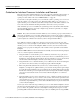
FEIP Installation Connect RJ-45, SC (FEIP-1FX or -2FX), or MII cables as follows: If you have MII connections, attach an MII cable directly to the MII port on the FEIP or attach a 100BASE-T transceiver, with the media appropriate to your application, to the MII port on the FEIP. (See Figure 18 for FEIP-2TX or Figure 19 for FEIP-2FX.
Attaching Fast Ethernet Interface Cables MII cable ER H9785 K II FIB M LIN ER FAST ETHERNET 0 II M FAST ETHERNET 0 LIN K Connecting MII or SC Cables (FEIP-2FX Shown, Horizontal Orientation) FIB Figure 19 or Simplex (2) To repeater To transceiver, repeater, or DTE Step 2 Duplex (1) To repeater For the 100BASE-TX RJ-45 connections, attach the ferrite bead to the RJ-45 cable (at either end), as shown in Figure 20.
FEIP Installation Using LEDs to Check FEIP Status The FEIP has four status LEDs on its faceplate that indicate status on each FE port. (See Figure 8.) LEDs (Partial Faceplate View of FEIP) H2941 Figure 21 After you connect cables, observe the LED states and the console display as the router initializes. When the system has reinitialized all interfaces, the enabled LED on the FEIP should go on. (For complete descriptions of the FEIP LEDs, refer to the section “FEIP LEDs” on page 15.
Configuring the Fast Ethernet Interfaces* Step 4 If an enabled LED still fails to go on, remove the FEIP and try installing it in another available interface processor slot. If the enabled LED goes on when the FEIP is installed in the new slot, suspect a failed backplane port in the original interface processor slot.
Configuring the Fast Ethernet Interfaces* Selecting Interface Processor Slot, Interface, and Interface Port Numbers This section describes how to identify interface processor slot, interface, and interface port numbers. Although the interface processor slots in the Cisco 7000, Cisco 7507, and Cisco 7513 are vertically oriented and those in the Cisco 7010 and Cisco 7505 are horizontally oriented, all models use the same method for slot and port numbering.
Configuring Interfaces—Descriptions and Examples Configuring Interfaces—Descriptions and Examples This section describes a basic configuration. Press the Return key after each step unless otherwise noted.
Configuring the Fast Ethernet Interfaces* FE half-duplex operation is the default. To change to full-duplex operation, use the following series of commands: Router# configure terminal Enter configuration commands, one per line. End with CNTL/Z. Router(config)# Router(config)# interface fastethernet 3/0/0 Router(config-if)# full-duplex Ctrl-z Note Each 100BASE-TX or 100BASE-FX interface on an FEIP can be configured at 100 Mbps, half duplex or full duplex, for a maximum aggregate bandwidth of 200 Mbps.
Checking the Configuration The RJ-45 connection is the default for FEIP-2TX (or SC for FEIP-2FX). To change to an MII connection and then verify it, use the following series of commands, including the media-type configuration command: Router# config t Enter configuration commands, one per line. End with CNTL/Z.
Configuring the Fast Ethernet Interfaces* Using show Commands to Display Interface Information To display information about a specific interface, use the show interfaces command with the interface type and port address in the format show interfaces [type slot/adapter/port]. Following is a partial-display example of how the show interfaces command displays status information (including the physical slot and port address) for the interface you specify.
Checking the Configuration The show controllers cbus command displays information about all of the interface processors in your router, including the FEIP.
Configuring the Fast Ethernet Interfaces* The show version (or show hardware) command displays the configuration of the system hardware (the number of each interface processor type installed), the software version, the names and sources of configuration files, and the boot images. Following is an example of the show version command used with a Cisco 7500 series system: Router# show version Cisco Internetwork Operating System Software IOS (tm) GS Software (RSP-JV-M), Released Version 11.
Checking the Configuration To determine which type of interfaces are installed on an FEIP in your system, use the show diag slot command. Specific interface information is displayed, as shown in the following example of an FEIP in interface processor slot 2: Router# show diag 2 Slot 2: Physical slot 2, ~physical slot 0xD, logical slot 2, CBus 0 Microcode Status 0x4 Master Enable, LED, WCS Loaded Board is analyzed Pending I/O Status: None EEPROM format version 1 FEIP controller, HW rev 2.
Upgrading FEIP Microcode Using the ping Command to Verify Network Connectivity The packet internet groper (ping) command allows you to verify that an interface port is functioning properly and to check the path between a specific port and connected devices at various locations on the network. This section provides brief descriptions of the ping command. After you verify that the system and FEIP have booted successfully and are operational, you can use this command to verify the status of interface ports.
Upgrading FEIP Microcode To compare the size of the microcode image and the amount of Flash memory available, you must know the size of the new microcode image. The image size is specified in the README file that is included on the floppy disk with the new image. Note Note the size of the new image before proceeding to ensure that you have sufficient available Flash memory for the new image. Caution Before you copy a file to system Flash memory, be sure there is ample space available in Flash memory.
Upgrading FEIP Microcode Step 4 Use the show flash command to verify that the microcode has been copied to Flash. The output should display the filename of the image you copied to Flash (vip11-1 in the following example): Router# show flash -#1 2 3 ED .. .. ..
Cisco Connection Online Cisco Connection Online Cisco Connection Online (CCO) is Cisco Systems’ primary, real-time support channel. Maintenance customers and partners can self-register on CCO to obtain additional information and services. Available 24 hours a day, 7 days a week, CCO provides a wealth of standard and value-added services to Cisco’s customers and business partners.
Cisco Connection Online 40 Fast Ethernet Interface Processor (FEIP) Installation and Configuration