
Specifications

Second-Generation Fast Ethernet Interface Processor (FEIP2) Installation and Configuration 21
What Is the FEIP2?
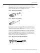
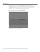
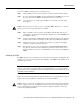
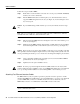
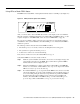
Figure 15 shows the duplex SC connector (one required for both transmit and receive), and Figure 16
shows the simplex SC connector (two required, one for each transmit and receive) used for
100BASE-FX optical-fiber connections on the FEIP2-2FX. These multimode, SC-type, optical-fiber
cables are commercially available; they are not available from Cisco Systems.
Figure 15 Duplex SC Connector (FEIP2-2FX)
Figure 16 Simplex SC Connector (FEIP2-FX)
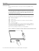
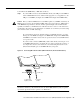
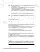
Depending on the type of media you use between the MII connection on the FE interface and your
switch or hub, the network side of your 100BASE-T transceiver should be appropriately equipped
with ST-type connectors (for optical fiber), BNC connectors, and so forth. Figure 17 shows the pin
orientation of the female MII connector on the FE interface.
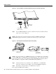
The MII receptacle (on both the FEIP2-2FX and FEIP2-2TX) uses 2-56 screw-type locks, called
jackscrews (shown in Figure 17), to secure the cable or transceiver to the MII port. MII cables and
transceivers have knurled thumbscrews (screws you can tighten with your fingers) that you fasten to
the jackscrews on the FEIP2’s MII connector. Use the jackscrews to provide strain relief for your
MII cable. (The RJ-45 modular plug has strain relief functionality incorporated into the design of its
standard plastic connector.) Figure 17 shows the MII female connector.
Figure 17 MII Connection, Receptacle (FEIP2-2FX and FEIP2-2TX)
H2214
H2399
Jackscrew Pin 1
Pin 21
H2943