
User guide


PTP 800 Series User Guide Managing 1+1 Hot Standby links
phn-2513_004v000 (Oct 2012)
7-49
Replacing the CMU on site
To replace the CMU on site, proceed as follows:
1
Identify the faulty CMU. The 1+1 LED state should be orange blink to indicate
that the CMU is faulty and not protecting.
2
Remove power cable from the faulty CMU, disconnect all other interface cables,
then remove the CMU.
3
Mount the replacement CMU.
If the installation includes a Fiber-Y interface, the CMU must have Fiber-Y
enabled before executing the remaining steps.
4
Connect interface cables to the replacement CMU (Figure 4), ensuring the
power cable is connected last:
a. Connect IF cable to RFU connector.
b. If configured for out-of-band management, connect the CMU
Management port to the appropriate CMU port of the 1+1 protection
splitter.
c. Connect copper data cable (if used) to copper Data port.
d. Connect SFP module and fiber cable (if used) to Fiber SFP port.
e. Connect ground cable to ground stud.
f. Connect power cable to -48 V DC power socket and power up.
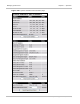
5
After approximately 2 minutes from powering up, check that the Management
port 1+1 LED state is either green steady (CMU is active) or green blink (CMU
is inactive). If it is in any other state, confirm that the correct CMU has been
replaced and re-check the CMU configuration. See Table 5 for details of CMU
LED states.