
User guide


PTP 800 Series User Guide Task 12: Aligning antennas
phn-2513_004v000 (Oct 2012)
6-103
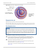
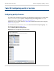
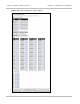
Figure 168 Typical RSSI voltage peaks and troughs
Aligning the other end
Repeat the above procedure at the other end of the link.
Record the RSSI voltage at both ends of the link. If the voltage at either end of the link is
not in the range predicted by the planning report, repeat alignment until this is the case.
Post-alignment actions
In a 1+1 Hot Standby link, the tolerances in the ODUs may result in the Receive Power
delta between the primary and secondary units at same end of the link being different
from the delta predicted by the network designer. Configurations using a single antenna
may have up to ±5 dB additional delta when compared with the design value. Where
separate antennas are used, the tolerances may increase if either path incurs any Excess
Path Loss.
When alignment is complete at both ends, proceed as follows:
1
At each end of the link in turn, lock off and tighten all the adjustment bolts as
per the instructions provided with the antenna and check that the RSSI voltage
does not change. If it does change, repeat alignment for the affected end.
2
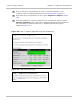
Check that the following requirements are met:
RSSI voltage at both ends is within the range predicted by the planning report.
Wireless Link Status is ‘Up’ (green) (Figure 169).
Receive Power at both end is within the range predicted by the planning report
(Figure 169).