
User guide

Task 12: Aligning antennas Chapter 6: Configuration and alignment
6-100
phn-2513_004v000 (Oct 2012)
Aligning a pair of antennas
Connect the CMUs to a management PC and open the web interfaces at both ends of the
link. For more information, see Connecting to the PC and powering up on page 6-6 and
Logging into the web interface on page 6-6.
When the Start Alignment option is selected, the Installation Wizard automatically
enables wireless transmission in alignment mode.
Antennas are aligned by monitoring RFU output voltage and receive power.
Align each pair of antennas by using Step 5, Step 6 and Step 7 of the Installation Wizard,
as described in the following procedures:
• Step 5: Starting antenna alignment on page 6-100
• Step 6: Aligning antennas on page 6-100
• Step 7: Completing alignment on page 6-105
Step 5: Starting antenna alignment
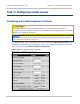
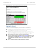
At both link ends, check that the Step 5: Start Antenna Alignment page is displayed
(Figure 150). If necessary, select menu option Installation Wizard and click through
Steps 1 to 4 of the wizard.
Step 6: Aligning antennas
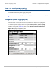
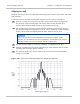
Select Start Alignment at both link ends. The Step 6: Antenna Alignment page is
displayed (Figure 166).
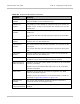
In the Step 6: Antenna Alignment page (Figure 166 and Figure 169), Transmit Power,
Receive Power, Vector Error and Link Loss are presented as an array of four elements.
These elements represent the maximum, mean, minimum and latest values respectively.
The maximum, mean and minimum are calculated over a running one hour period.
During the alignment process, ensure that antenna waveguide and coaxial components
are not strained beyond their minimum bend radii.