
User guide

Task 12: Aligning antennas Chapter 6: Configuration and alignment
6-98
phn-2513_004v000 (Oct 2012)
Task 12: Aligning antennas
Use the Installation Wizard to set the system into alignment mode, to achieve the lowest
possible link loss through correct antenna alignment, and to report on the performance of
the configured link.
Do not start antenna alignment until it is safe for the antennas to radiate RF,
that is, until the antennas and ODUs have been installed on the masts or poles
and no personnel are in front of the antennas.
For background on the alignment process, refer to Introduction to antenna alignment on
page 6-98.
Check that the requirements in Prerequisites for alignment on page 6-99 have been met.
For a 1+1 Hot Standby link with two antennas at each end of the link, perform Aligning
protected antennas on page 6-99.
For an unprotected link, or for a 1+1 Hot Standby link that uses ODU couplers, perform
Aligning a pair of antennas on page 6-100.
Introduction to antenna alignment
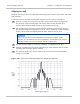
Licensed microwave links use parabolic dish antennas which have narrow beam widths
ranging from 4.7° down to 0.5°. Beam width depends on antenna gain, larger gain
antennas having narrower beam widths. It is most important that all PTP 800 antennas are
precisely aligned at the centre of the main beam. If antennas are not aligned at the centre
of the main beam, performance will be dramatically reduced.
The alignment process requires the elevation angle (vertical plane) and azimuth angle
(horizontal plane) to be adjusted. Antenna assemblies provide a mechanism for
independently adjusting in both planes whilst the antenna mounting bracket is securely
mounted to the mast. Please refer to the instructions provided with the antenna.
Alignment is achieved by monitoring the receive signal strength indicator (RSSI). This is
provided at the RFU BNC socket in the form of a dc voltage (RSSI Voltage).