
User guide

PTP 800 Series User Guide Preparing network connections (1+1 Hot Standby)
phn-2513_004v000 (Oct 2012)
5-89
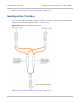
Preparing network connections (1+1 Hot Standby)
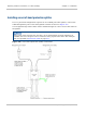
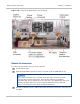
This section describes how to prepare the cables to connect the CMU to the Ethernet
switch in the customer and (optionally) management networks. It applies only to protected
ends (1+1 Hot Standby links).
The CMU is not normally connected to the network equipment until antenna alignment is
complete. See Task 15: Connecting link to the network on page 6-114.
Select and install the required interfaces depending on the choice of management mode
and network connection (Table 218).
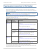
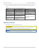
Table 218 Selecting network interfaces for 1+1 Hot Standby links
Management
mode
Network
connection
Procedures
Out-of-band
(Figure 59)
Customer data Either: Installing a redundant copper interface on
page 5-91;
Or: Installing a redundant fiber interface on page 5-
92;
Or: one copper and one fiber (*1);
Or: Installing a Fiber-Y interface on page 5-93.
Management data
(not ‘last hop’)
Installing an out-of-band protection splitter on page
5-90
Management data
(‘last hop’)
(*2)
Either: Installing an out-of-band protection splitter
on page 5-90, but connect the two LAN ports
together using a protection cable;
Or: Installing a protection cable on page 5-94.
In-band
(Figure 61)
Customer data Either: Installing a redundant copper interface on
page 5-91;
Or: Installing a redundant fiber interface on page 5-
92;
Or: one copper and one fiber (*1).
Management data Installing a protection cable on page 5-94
(*1) It is possible to combine the two types of redundant interface at one link end, that is,
connect one CMU to the network via copper and the other CMU via fiber.
(*2) ‘Last hop’ link ends are those that are at the edge of the network, where access to the
management network is not always available.