
User guide
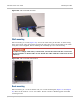
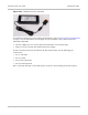


Installing the CMU Chapter 5: Installation
5-82
phn-2513_004v000 (Oct 2012)
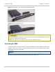
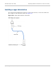
ODU-based deployments
Cut any surplus length from the CMU end of the ODU-CMU IF cable and fit an N type
connector, as described in Fitting an N type connector to an IF cable on page 5-38.
Connect this IF cable to the CMU.
For 1+1 and 2+0 links, repeat for the second ODU and CMU.
For an ODU-based 1+1 Hot Standby link with an asymmetric coupler, make the following
connections:
1) Connect the IF cable from the ‘MAIN’ side of the ODU coupler to the CMU labelled
‘Primary’.
2) Connect the IF cable from the ‘STANDBY’ side of the ODU coupler to the CMU
labelled ‘Secondary’.
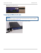
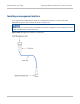
IRFU-based deployments
Connect the supplied IF cable (Cambium part number 30009403001) to the CMU.
For 1+1 and 2+0 links, repeat for the second transceiver unit and CMU.
For an IRFU-based 1+1 Hot Standby link with the unequal coupling option, make the
following connections:
1) Connect the IF cable from the primary (left hand) transceiver to the CMU labelled
‘Primary’.
2) Connect the IF cable from the secondary (right hand) transceiver to the CMU labelled
‘Secondary’.
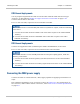
Connecting the CMU power supply
Connect the CMU to a minus 48 Volt (−48V) supply capable of supplying a maximum of 2
amps.
The Cambium supplied AC to DC converter is shown in Figure 101. For specifications of
the converter, mains cables and DC connectors, refer to AC to DC converter specifications
on page 4-4.