
User guide


Testing the ODU and IF cable Chapter 5: Installation
5-62
phn-2513_004v000 (Oct 2012)
To prepare for pre-power testing, proceed as follows:
1
Connect the analyzer to the first LPU (Figure 81).
2
Connect the first LPU to the second (Figure 81).
3
Check that the second LPU is disconnected from the cable that leads to the ODU
(Figure 81) (the second LPU and ODU are reconnected during testing).
4
Power on the analyzer.
When these preparations are complete, perform the following tests:
• Testing cable loss on page 5-62.
• Measuring distance to fault on page 5-67.
Testing cable loss
The purpose of this test is to ensure that the total cable loss is within acceptable limits.
Before performing this test, ensure that the test equipment is set up as described in Test
preparation on page 5-61.
To measure cable loss, proceed as follows:
1
Select the ‘cable loss-one port’ mode of the cable analyzer (Figure 80).
2
Set the frequency of measurement to:
F1 = 350MHz
F2 = 400MHz.
3
Calibrate the instrument for the selected frequencies, using the correct
calibration kit.
4
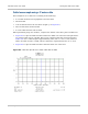
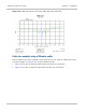
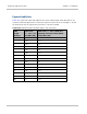
Before connecting the ODU, obtain a plot of cable loss and check that it is within
the expected limits for the given cable length (Table 215). Compare it to
examples of good installations (Figure 82 and Figure 84).
5
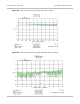
Connect the ODU.
6
Observe the effect of the ODU connection on the plot of cable loss.
Compare it to examples of good installations (Figure 83 and Figure 85).
If there is little or no change to the plot when the ODU is connected, it indicates
a short or open circuit on the cable.
7
Keep a copy of the cable loss plots so that they can be compared with
subsequent plots to determine if there is any degradation with time.