
User guide


PTP 800 Series User Guide Planning 2+0 links
phn-2513_004v000 (Oct 2012)
2-55
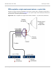
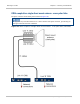
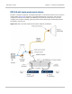
Network configurations for 2+0
In a 2+0 configuration, Link ‘A’ and Link ‘B’ are independent. Each CMU is connected to
the network using one of the methods described in Network configurations for 1+0 on
page 2-34. The two links may be managed in different ways, for example Link ‘A’ may be
out-of-band and Link ‘B’ may be in-band.
Frequency spacing in 2+0 ODU based links
For co-polar deployments, the transmit frequency of link A and link B at a given end must
be separated by at least two channel separations. For example, if the channel separation is
configured as 28 MHz, the spacing between the two transmit frequencies must be at least
56 MHz.
For cross-polar deployments, the transmit frequency of link A and link B at a given end
must be separated by at least one channel separation. For example, if the channel
separation is configured as 28 MHz, the spacing between the two transmit frequencies
must be at least 28 MHz.
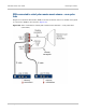
Frequency spacing in 2+0 IRFU based links
In a 2+0 IRFU-based link, plan the four transmit frequencies to meet the following
requirements:
• At each link end, the two transmit frequencies must be separated by at least the
amount quoted in Table 13.
• At each link end, the transmit and receive frequencies must be separated by at least
the amount quoted in Table 14.
Table 13 Minimum transmit/transmit frequency separation at a 2+0 IRFU link end
Channel bandwidth Band RF filter
bandwidth
Minimum separation between
transmit frequencies
25, 30, 40 MHz 6 GHz,
11 GHz
30 MHz 70 MHz
40 MHz 80 MHz
10 MHz 6 GHz 30 MHz 40 MHz
10 MHz 11 GHz 30 MHz 60 MHz
40 MHz 70 MHz