
User guide


PTP 800 Series User Guide Planning 1+1 Hot Standby links
phn-2513_004v000 (Oct 2012)
2-43
Network configurations for 1+1
1+1 Hot Standby link management
In a 1+1 Hot Standby Link, each CMU is managed separately and must be assigned its
own IP address.
Choosing Ethernet switches
The Ethernet switch must react to a brief disconnection of an Ethernet port by flushing its
forwarding data base (see Bridging in 1+1 links on page 1-66). This allows the Ethernet
switch to learn the new bridging path following a protection switch. When choosing an
Ethernet switch, ensure that this feature is supported.
Many inexpensive unmanaged switches fail to meet this requirement.
The switch must support the required number of ports for 1+1 Hot Standby operation.
This is dependent on the following factors:
• Whether copper or fiber is the physical connection medium or whether the Fiber-Y
option is required.
• Whether in-band or out-of-band management mode is required.
The details of these requirements are in the following sections.
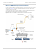
1+1 Hot Standby link with out-of-band management
Out-of-band management provides two separate networks, one for customer data and one
for managing the network. Please refer to Management network on page 1-43 for more
details on out-of-band Management.
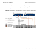
When Out of Band management is selected, the Ethernet switch must provide two ports in
order to carry the management traffic to both CMUs. As the protection interface shares
the same physical socket as the management port, an Out of Band Protection Splitter is
required to route the management traffic from the two CMUs to the Ethernet switch.
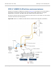
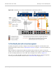
For the customer data, there are two methods of connection, either redundant data ports
or Fiber-Y.
For redundant data ports, the Ethernet switch must provide two ports for carrying
customer data traffic to both CMUs. The choice of physical medium can be copper or fiber
and this can be selected independently for each CMU. This arrangement is shown in
Figure 59.