
Programming instructions

50
3300 ICP Technician’s Handbook
5. Remove the cover plate from the selected slot by removing the two
screws that hold the plate in place.
6. If the interface assembly has an extension bracket, mount the
interface assembly extension bracket on the selected slot using the
screws that secured the cover plate. The closed side of the extension
bracket must be to the left when viewed from the rear of the cabinet.
7. Insert the interface assembly into the empty slot in the DSU box.
Ensure that the edge connector on the card aligns with the connector
on the backplane of the system.
8. Secure the interface assembly to the DSU cabinet or the extension
bracket.
Install the DSU Cards
To install a DSU card:
1. Ensure that the FIMs are installed and cabled.
2. Connect the power cord to the external AC power source.
3. Unpack the card, and verify that it is not damaged.
4. If required, adjust the card switch settings (see page 289 for details).
5. Check the connector pins to be certain that they are straight.
6. Slide the card into the appropriate slot.
7. Push the upper and lower latches away from you until they are vertical
and the card is locked in place.
8. Proceed to one of the following tasks to complete the card installation:
- CEPT or DS1 formatter cards (see page 154)
- BRI card (see page 152)
- PRI card (see page 154)
- R2 card (see page 158)
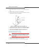
Tip: When you are facing the rear panel, the DSU box slots (from right to
left) correspond to DSU slots 2 through 5.
CAUTION: To prevent static damage to electrical compo-
nents, ensure that the system is grounded. Whenever you
handle circuit cards, wear an anti-static strap.