
Programming instructions

49
Installation
Connect the Fiber Cable to the DSU Node
The fiber optic cable connects the FIMs in the controller to the FIMs in the
DSU node.
To connect the fiber optic cable to the FIM in the DSU node:
1. Route the fiber optic cable through the cable port at the rear of the
DSU cabinet. Extend the fiber cable approximately 1 ft (30 cm) beyond
the front of the cabinet.
2. Install a short piece of nylon spiral wrap over the cable at the point
where the cable exits the rear of the cabinet.
3. Close the sliding cable port door. Ensure that the door closes on the
nylon spiral-wrapped section of fiber cable.
4. Remove the plastic dust caps from the fiber optic cable connectors
and the connector ferrules on the FIM faceplate.
5. Plug the fiber optic cable connectors into the connector ferrules on the
FIM faceplate.
Install the Interface Assemblies
The DS1 interface assembly provides two filtered DB-15 pin connectors
for the external cables required by one DS1 formatter card. You can mount
up to four DS1 interface assemblies in the DSU.
The CEPT interface assembly provides four filtered BNC connectors for
the external cables required by one formatter card. You can mount up to
four CEPT interface assemblies in the DSU. Each interface assembly
plugs into a J3 DIN 3x32 pin connector. The connectors are located in a
3.5 inch x 5 inch (9 cm x 12.5 cm) box that projects from the backplane.
To install a DSU Interface Assembly:
1. Attach an anti-static strap to your wrist.
2. Unpack and inspect the interface assembly.
3. If you are installing a CEPT Interface Assembly, set the jumpers to the
desired positions.
4. At the rear of the cabinet, locate the slot in the DSU box that
corresponds to the DSU slot that you will use for each DSU card.
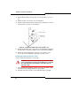
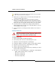
Tip: The fiber optic cable connectors have a small key that you must align
with a slot on the FIM connectors. Lock each connector into position by
pushing its metal collar forward and clipping it onto the FIM connector.