
Programming instructions

47
Installation
4. Remove the black plastic dust caps from the fiber optic cables and the
connector ferrules on the unit.
5. Connect the fiber optic cables from the peripheral slot FIM carrier in
the peripheral cabinet to the connectors on the SUPERSET HUB unit.
6. Connect the RJ-45 connectors to the UTP distribution panel according
to the building wiring plan.
7. Connect the power cable to a convenient wall socket.
8.
Program the SUPERSET HUB as a DNI line card in the slot where the
peripheral slot FIM carrier is inserted.
Digital Service Unit
Tip: Because the power cable is the main disconnect device, the wall socket
must be near the unit and easily accessible.
Tip: When installing the SUPERSET HUB in an enclosed rack, you must
provide adequate ventilation to ensure that the maximum ambient
temperature inside the rack does not exceed 40ºC (104ºF).
Tip: When mounting the SUPERSET HUB in a rack, ensure that a hazardous
condition is not achieved due to any uneven mechanical loading.
Tip: When using the SUPERSET HUB in a rack, consider the connection of
the equipment to the supply circuit and the effect that overloading of circuits
might have on overcurrent protection and supply wiring. When addressing
this concern, consider the SUPERSET HUB’s ratings label.
WARNING:DO NOT APPLY POWER TO THE EQUIPMENT AT
ANY TIME DURING EQUIPMENT INSTALLATION.
Tip: The CX and CXi controllers do not support Digital Service Units.
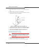
Tip: Two DSU cabinets may be programmed in a single DSU node. On the
left side of the node, slots 1, 2, and 3 comprise one DSU cabinet. On the
right side of the node, slots 4, 5, and 6 comprise another DSU cabinet. When
you program cards in the left cabinet, program slot 3 before slot 2. When
you program cards in the right cabinet, program slot 5 before slot 4. If you
do not follow this order of programming, the DSU cards on the side of the
node that you are programming will reset when you add the second card and
the cabinet will go out of service for one or two minutes.