
Programming instructions

41
Installation
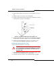
5. Connect an external ground to the ground terminal on the rear panel
of the peripheral cabinet. Refer to the Safety Instructions for detailed
grounding requirements. These instructions are packaged with each
system.
6. Remove the peripheral cabinet front panel (see “Removing/Replacing
the Front Panel of a Peripheral Cabinet or DSU” on page 142).
Check the Card Layout
Typically, a peripheral cabinet is shipped with the peripheral switch
controller (PSC) card and fiber interface module (FIM) installed. If these
cards were not shipped in the cabinet, see page 142 for installation
instructions. You must install and cable the FIM before you install the
peripheral switch controller card and power converter.
Install the cards in the following configuration (see also page 280).
CAUTION: Do NOT apply power to the peripheral cabinet
until you have installed the ground cable.
Slot Number Card Type
1 to 12 Peripheral interface card
13, 14, 15 (combined) Power converter
16 Peripheral switch controller (PSC)
17 Fiber interface module (FIM)
Note: Depending on the peripheral cabinet type, slots 16, 16B, and 17 may be
used for the following purposes:
• Type A (9400-200-110-NA) has a peripheral switch controller (PSC) card in
slot 16 that works in conjunction with a peripheral resource card (PRC) in the
upper portion of slot 17. A fiber interface module (FIM) is located in the lower
portion of slot 17.
• Type B (9400-200-113-NA) has a PSC or PSC II card in slot 16. The PSC
card works in conjunction with a PRC in slot 17; a PSC II card includes PRC
functionality. A FIM is located in the lower portion of slot 17.
• Peripheral cabinet II or peripheral cabinet 19" has a PSC II in slot 16 and a
FIM in slot 17.
Tip: If you are installing an expanded peripheral cabinet, or expanding an
existing one, the card layout will be different depending on whether the
cabinet is used as the master or slave of the peripheral pair. Refer to
“Installing an Expanded Peripheral Cabinet” on page 149.