
Programming instructions


378
3300 ICP Technician’s Handbook
Capacity
Hardware Capacity
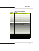
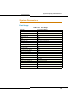
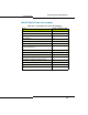
The following tables provide a view of the maximum capacity of the 3300
ICP. The capacities in these table are for a non-resilient 3300 ICP.
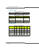
Tip: The capacities in Table 135 are not true hardware limitations, but may
be limits set by software. Most systems will reach practical operational
limitations before these large numbers of devices are reached.
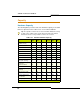
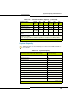
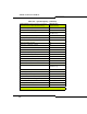
Table 135: 3300 ICP Hardware Capacity
Parameter Name LX/700
User
250
User
MX MXe
(Note 2)
100
User
CX /
CXi
Compression Channels
(TDM-IP G.729a)
64 64 32 32/64 32 16
DTMF Receivers 128 128 128 128 128 128
E2T Channels 128 64 64 64/128 64 64
Tone Detector Circuits 32 32 32 32 32 32
Tone Generators 128 128 128 128 128 128
Voice Mail Ports 30 30 30 30 30 16
Dual FIMs 4 3 2 4 1 n/a
T1/E1 Modules 3 3 2 3 1 2
NSUs (without chaining)
NSUs (with chaining)
4
8
4
8
2
4
4
8
2
4
n/a
Peripheral Cabinet (direct
connection)
Expanded Cabinet
6
12
3
6
3
6
6
12
2
n/a
n/a
ASUs 4 4 2 4 2 n/a
Trunks (analog and digital
combined)
628 628 628 628 628 628
BRI U Interfaces (with
NSU)
60 60 30 60 30 n/a
IP Trunks between any
two controllers
200 200 200 200 200 200
ACD Agents (see Note 1) 350 200 100 350 80 50
(Page 1 of 2)