
Programming instructions

358
3300 ICP Technician’s Handbook
DSU PRI Card
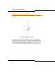
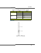
Three status LEDs and 14 circuit LEDs are mounted on the PRI card
faceplate. Each of the card circuit LEDs shows the status of one PRI
circuit.
Figure 101: DSU PRI Card LEDs
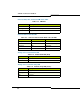
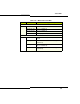
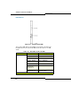
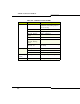
Table 123: DSU PRI Card Circuit LEDs
LED State Meating
L0 and L1 right side - solid red error
right side - off no error
left side - solid green D-channel established
left side - flashing
green
Layer 1 established
left side - off no link
right side - yellow
with left side -
flashing green
alarm indication from far end
right side - yellow
with left side - off
blue alarm from card - normal
during link startup
(Page 1 of 2)