
Programming instructions

277
Hardware Reference
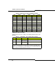
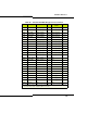
Table 65: ASU II Combo Card SFT/PFT Port Connections
LS Port ONS Port
11
2 2
33
4 4
Note: Up to four SFT/PFT calls can occur at the same time between pairs of LS
and ONS ports. ONS is supported against an LS trunk.
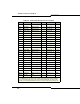
Table 66: Universal ASU Music on Hold Connector Pinout
Pin Signal Virtual Circuit
1/2 Tip/Ring 1 n 1 4 1
3/6 Tip/Ring 2 n 1 4 2
4/5 Tip/Ring 3 n 1 4 3
7/8 Tip/Ring 4 n 1 4 4
Note: CIM 1: n = 2. CIM 2: n = 3.
Note: The four MOH tip/ring pairs occupy an 8-pin female modular jack on the rear panel.
MOH can be assigned to either of the first two ports on a Universal ASU E&M card.
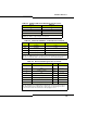
Table 67: Universal ASU Pager Connector Pinout
Pin Signal Zone
Virtual Circuit
1 Tip 00 n 1 5 1
2 Ring 00 n 1 5 1
3 Common contact 00
4 Tip 01 n 1 5 2
5 Ring 01 n 1 5 2
6 Normally open contact 00
7 Common contact 01
8 Normally open contact 01
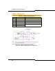
Note: CIM 1: n = 2. CIM 2: n = 3.
Note: The Paging port is a standard 8-pin modular RJ-45 connector on the rear panel.
Note: Each paging port has a tip/ring pair for audio and a second tip/ring pair contact
closures for zone control. The contact closes when paging on zones.