
Programming instructions

272
3300 ICP Technician’s Handbook
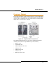
BRI NSU DIP Switch Settings
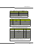
Table 61 below shows the settings for the CEPT port DIP switch for the
BRI NSU.
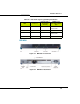
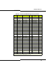
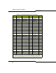
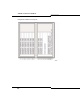
Table 60: BRI Connector Pinout (Amphenol 25-pin)
Pin Signal Pin Signal Pin Signal
1 T1 11 T11 31 R6
2 T2 12 T12 32 R7
3 T3 13 T13 33 R8
4 T4 14 T14 34 R9
5 T5 15 T15 35 R10
6 T6 26 R1 36 R11
7T727R237R12
8 T8 28 R3 38 R13
9T929R439R14
10 T10 30 R5 40 R15
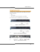
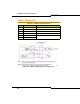
Table 61: CEPT Mode - E1 Port DIP Switch Settings
Switch Use Setting Notes
1 Tx Ground Up: Floating
Down: Ground
Not required for RJ-45 connector.
2 Rx Ground Up: Floating
Down: Ground
Not required for RJ-45 connector
Note: This setting is site-dependent. Normally Tx is grounded and Rx is not
grounded, but that depends on which remote connection is grounded. These
switches are used only with the coaxial adapter; leave up (floating) with twisted
pair connection. Not required for RJ-45 connector.