
Programming instructions

269
Hardware Reference
Universal and R2 NSU Pin Allocations
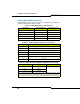
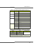
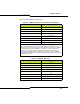
Table 55: CIM Port Connector (Controller, NSU and ASU)
RJ-45 Connector Pin Signal Name
1RX+
2 RX-
3TX+
4 Not used
5 Not used
6 TX-
7 Not used
8 Not used
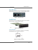
Note: The Universal ASU connects to the controller over a Category 5
Universal Twisted Pair (UTP) crossover cable through a CIM interface. The
Category 5 cable is of the same type used for Ethernet connections and within
the cable twisted pairs are arranged as: 1,2: 3,6; 4,5; 7,8. Each tied pair is
connected to a 75 ohm resistor. The Universal ASU can be located up to 30
meters (98.4 feet) away from the controller. The interface employs a single
standard 8-pin modular jack consisting of 2 balanced signal pairs and is located
on the front of the unit.
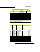
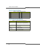
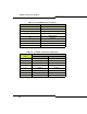
Table 56: Ethernet Connector
RJ-45 Connector Pin Signal Name
1TX+
2 TX-
3RX+
4 Not used
5 Not used
6 RX-
7 Not used
8 Not used