
Programming instructions

160
3300 ICP Technician’s Handbook
3. Plug the R2 cable(s) into the network terminating equipment.
See Table 74 on page 292 for the R2 card RJ-45 connector pinout.
Testing the R2 Card
If the installation is successful, the R2 card will boot up, configure itself with
the default database and communicate with the system.
To test the R2 card:
1. Inspect the LEDs on the faceplate to verify that the card is functioning.
See Faceplate LEDs on page 359.
2. Log into the System Administration Tool (see page 8).
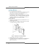
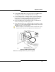
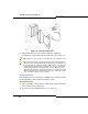
Figure 29: R2 Card Connections
Tip: A dual-port card needs two coaxial cables if you are using both ports.
Tip: The R2 coaxial cables have both transmit (arrow pointing away from
cable) and receive (arrow pointing towards cable) connectors. When you set
the card for trunk side termination (jumper at NT position), connect the R2
coaxial cable transmit lead to the network receive connector, and the R2
coaxial receive lead to the network transmit connector. When you set the
card for line side termination (jumper at LT position), connect the R2 coaxial
cable transmit lead to the network transmit connector, and the R2 coaxial
receive lead to the network receive connector.