
Programming instructions

150
3300 ICP Technician’s Handbook
4. Install up to 12 peripheral interface cards in slots 1 to 12 of each
cabinet, as required for your system.
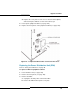
5. Attach an EMI filter kit to the back of the master cabinet:
a. Remove the sliding door from the back of the cabinet and attach
the filter kit using the screws from the sliding door (route the
attached filter cable through to the front of the cabinet).
b. Attach the cable to the front of the peripheral interconnect card.
c. Loosen the door screws on the back of the filter kit and slide the
door up. Follow the steps in Connect the Fiber Optic Cable.
d. Tighten the door screws on the back of the filter kit to hold the FIM
cables securely in place.
6. Cable the cabinet to the MDF (see page 45) and power it up to ensure
it works properly.
7. Repeat step 5, attaching the remaining EMI filter kit to the slave
cabinet (skip steps c and d since there is no FIM installed in the slave
cabinet).
8. Attach the cabinet interconnect cable to each EMI filter kit, connecting
the two cabinets together.
9. Power up the slave cabinet and ensure it works properly.
10. Replace the front panels of each cabinet (see page 142).
Replacing a Peripheral Switch Controller Card
To replace a peripheral switch controller card:
1. Power down the peripheral cabinet (see page 142).
2. Replace the faulty peripheral switch controller card with the new
peripheral switch controller card.
3. Power up the peripheral cabinet (see page 142).
CAUTION: Wear an anti-static strap whenever you handle
circuit cards.