
Programming instructions

148
3300 ICP Technician’s Handbook
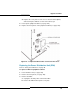
4. Remove the PSC from slot 16 in the slave cabinet, and replace it with
a peripheral interconnect card. The PSC is not required.
5. Attach an EMI Filter Kit to the back of the slave cabinet:
a. Remove the sliding door from the back of the cabinet.
b. Attach the filter kit using the screws from the sliding door.
c. Route the attached filter cable through to the front of the cabinet.
d. Attach the cable to the front of the peripheral interconnect card.
6. Install up to 12 peripheral interface cards in slots 1 through 12 of the
slave cabinet (as required for your system).
7. Proceed to connect an expanded peripheral node II to a peripheral
node II (see steps below).
To connect an expanded peripheral cabinet II to peripheral cabinet II:
1. Convert a peripheral cabinet II to an expanded peripheral cabinet II
(see steps above).
2. Unpack, position, and ground the master cabinet.
3. Remove the front panel from the master cabinet.
4. Detach the fiber cables from the FIM in the master cabinet, and
remove them through the cable port on the back of the cabinet.
5. Install the additional peripheral interconnect card in slot 16B of the
master cabinet.
6. Attach an EMI filter kit to the back of the master cabinet:
a. Remove the sliding door from the back of the cabinet.
b. Attach the filter kit using the screws from the sliding door.
c. Route the attached filter cable through to the front of the cabinet.
d. Attach the cable to the front of the peripheral interconnect card.
e. Loosen the door screws on the back of the filter kit and slide the
door up.
f. Follow the steps in Connect the Fiber Optic Cable.
Tip: The master cabinet includes a power converter in slots 13 through 15,
a PSC in slot 16, and a FIM in slot 17. The slave cabinet includes a power
converter in slots 13 through 15 and a peripheral interconnect card in slot
16. An additional peripheral interconnect card and EMI filter are also available
from the peripheral node expansion kit.