
Programming instructions

135
Upgrades and FRUs
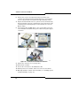
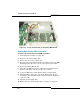
7. Remove the two screws from the hold-down for the Amphenol cable
assembly on the back of the unit.
8. Remove the clock module, behind MMC Slot 2.
9. Remove the Analog Main Board.
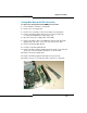
10. Insert the new Analog Main Board.
11. Replace the two screws in the hold-down for the Amphenol cable
assembly on the back of the unit.
12. Replace the two screws at the front of the board and the four standoffs.
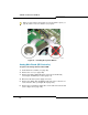
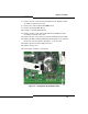
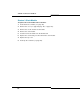
13. Replace the ribbon cable by sliding it under the guides on the side and
up into the connector. Flip the clip down to secure the cable.
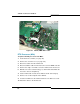
14. Replace the three Power Supply connectors.
15. Replace the top cover.
16. Power up the controller (see page 22).
Figure 22: Analog Main Board Ribbon Cable