
Programming instructions

112
3300 ICP Technician’s Handbook
9. Reconnect the cables to the controller. Power up the controller.
Echo Canceller
To add or replace an echo canceller:
1. Power down the controller (see page 99).
2. Disconnect all cables.
3. Remove the cover (see page 99, page 100, or page 101).
4. Remove the echo canceller module from its packaging.
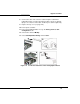
5. If you are replacing a defective echo canceller module, remove the
screws and lock washers and pull up on the module to remove it.
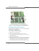
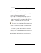
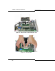
6. Line up the connectors of the new echo canceller module and firmly
seat it onto the main board in an appropriate slot (see page 15).
7. Secure the module onto the main board using the screws and lock
washers provided.
8. Replace the controller top cover and secure it with its screws (see “To
install the LX/700-user controller cover:” on page 100, “To remove the
MX/100-user controller cover:” on page 100, or “Removing/Replacing
CX/CXi/MXe Controller Cover” on page 101).
9. Reconnect the cables to the controller.
10. Power up the controller (see page 22).
Tip: For the T1/E1 Combo, connect the T1 line from the service
provider to the RJ45 connector on the T1/E1 combo module. See
Table 40 on page 260 for connector pinouts
.
Tip: The Quad BRI Framer allows a 1:1 connection to a BRI Central
Office or a crossover connection to a BRI telephone. The shielded,
twisted pair ISDN cable is connected on either end with pins 3-4, and
5-6. The straight-through cable is used for “T” interfaces to the
Central Office and the crossover (with 3-4 and 5-6 crossed at one
end) for “S” interfaces to sets
.
Tip: The CX, CXi, and MXe controllers contain echo cancellers on the main
board sufficient to handle normal traffic conditions.