Meraki CW9166I‐MR, CW9164I‐MR Hardware Installation Guide
Trademarks Meraki, Meraki CW9166I‐MR, CW9164I‐MR, Meraki Cloud Controller, and Meraki Mesh are trademarks of Cisco Systems, Inc. Other brand and product names are registered trademarks or trademarks of their respective holders. Statement of Conditions In the interest of improving internal design, operational function, and/or reliability, Cisco Systems reserves the right to make changes to the products described in this document without notice.
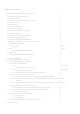
Table of Contents 1 Scope of Document and Related Publications 4 2 CW9166I‐MR, CW9164I‐MR Overview 2.1 Package Contents 2.2 Understanding the CW9166I‐MR, CW9164I‐MR 2.3 Security Features 2.4 Ethernet Ports 2.5 Power Source Options 2.6 Factory Reset Button 2.7 LED Indicators and Run Dark Mode 5 5 5 7 7 7 7 7 3 Pre‐Install Preparation 3.1 Configure Your Network in Dashboard 3.2 Check and Upgrade Firmware 3.3 Check and Configure Firewall Settings 3.4 Assigning IP Addresses to CW9166I‐MR, CW9164I‐MRs 3.
1 Scope of Document and Related Publications The CW9166I‐MR, CW9164I‐MR Hardware Installation Guide describes the installation procedure for the CW9166I‐MR, CW9164I‐MR indoor access point. Additional reference documents are available online at www.meraki.com/library/product.
2 CW9166I‐MR, CW9164I‐MR Overview The Meraki CW9166I‐MR, CW9164I‐MR is an enterprise‐class, dual‐concurrent 4x4 MIMO 802.11ax indoor access point designed for high‐density deployments in offices, schools, hospitals and hotels. When connected to the Meraki Cloud Controller, the CW9166I‐MR, CW9164I‐MR enables the creation of ultra‐high speed, reliable indoor wireless networks quickly, easily and cost‐ effectively. 2.
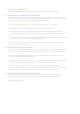
Your CW9166I‐MR, CW9164I‐MR mount plate has the following features: Access point mounting posts (2x) Various mounting holes 6
2.3 Security Features The CW9166I‐MR, CW9164I‐MR features multiple options for physically securing the access point after installation: 1. Security screw – The accessory kit includes screws that can be used to secure the access point to the mount plate. Engaging the security screw prevents accidental dislodging and theft. 2. Kensington lock – The access point contains a hard point that allows it to be secured to any nearby permanent structure using a standard Kensington lock. 2.
3 Pre‐Install Preparation You should complete the following steps before going on‐site to perform an installation. 3.1 Configure Your Network in Dashboard The following is a brief overview only of the steps required to add an CW9166I‐MR, CW9164I‐MR to your network. For detailed instructions about creating, configuring and managing Meraki wireless networks, refer to the Meraki Cloud Controller Manual (meraki.com/library/product). 1. Login to http://dashboard.meraki.com.
3.4 Assigning IP Addresses to CW9166I‐MR, CW9164I‐MRs All gateway CW9166I‐MR, CW9164I‐MRs (CW9166I‐MR, CW9164I‐MRs with Ethernet connections to the LAN) must be assigned routable IP addresses. These IP addresses can be dynamically assigned via DHCP or statically assigned. 3.4.1 Dynamic Assignment When using DHCP, the DHCP server should be configured to assign a static IP address for each MAC address belonging to a Meraki AP. Other features of the wireless network such as 802.
3.5 Collect Tools You will need the following tools to perform an installation: Phillips screwdrive r Hammer Drill with 1/4” (6.3mm) bits 3.6 Collect Additional Hardware for Installation or 802.3at PoE power source (either PoE switch or Meraki 802.
4 Installation Instructions 4.1 Choose Your Mounting Location A good mounting location is important to getting the best performance out of your CW9166I‐MR, CW9164I‐MR access point. Keep the following in mind: 1. The device should have unobstructed line of sight to most coverage areas. For example, if installing in an office filled with workspaces divided by mid‐height cubicle walls, installing on the ceiling or high on a wall would be ideal. 2.
4.2.1.1 Wall or Solid Ceiling Mount Using Mount Plate Using included screws, attach the mount plate to your mounting wall or ceiling. It is recommended that the CW9166I‐MR, CW9164I‐MR be mounted to a wall or solid ceiling using the mount plate for physical security reasons. If mounting your CW91661-MR to a wall, skip to “Power the CW91661-MR“ on P.
4.2.1.2 Electrical Junction Box Mount Using Mount Plate The CW9166I‐MR, CW9164I‐MR can be mounted to a 4” square cable junction box, a 3.5 or 4” round cable junction box, or various U.S. and European outlet boxes (mounting screws are not included). Using appropriate mounting hardware for your specific type of junction box, attach the mount 4.2.2 Power the CW9166I‐MR, CW9164I‐MR If mounting to an electrical junction box, feed the Ethernet cable through the cable access hole in the Mount Plate.
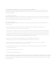
4.2.2.1 Powering the CW9166I‐MR, CW9164I‐MR with the Meraki AC Adapter (sold separately) 1. Plug the power cord into the CW9166I‐MR, CW9164I‐MR and the other end into a wall outlet. 2. Plug an Ethernet cable that is connected to an active Ethernet connection into the Eth0 port on the CW9166I‐MR, CW9164I‐MR. 4.2.2.2 Powering the M410‐MR with the Meraki 802.3at Power over Ethernet Injector (sold separately) 1. Plug the power cord into the PoE Injector and the other end into wall power. 2.
4.2.2.3 Powering the CW9166I‐MR, CW9164I‐MR with an 802.3at Power over Ethernet Switch Route Ethernet cable from a port on an active 802.3at PoE switch to the Eth0 port in the bay of the CW9166I‐MR, CW9164I‐MR. The CW91661-MR is Gigabit Ethernet-capable. To maximize device performance, a Gigabit-capable switch should be used. 4.2.
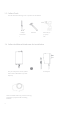
4.2.3.2 Assemble CW9166I‐MR, CW9164I‐MR to the Mount Plate (This section applies to wall and/or solid ceiling, drop ceiling or electrical junction box mount where you have already installed the mount plate.) Insert the top latch on the mount plate into the top mount plate attachment slots on the back of the device. Rotate the bottom of the unit into the bottom mount plate attachment slot. The unit will click into place.
4.2.3.3 Desk or Shelf Mount The CW9166I‐MR, CW9164I‐MR can be placed on a desk or shelf resting on the non‐scratch rubber feet. The mount plate is not necessary for a desk or shelf mounting.
4.3 Secure the CW9166I‐MR, CW9164I‐MR Depending on your mounting environment, you may want to secure the CW9166I‐MR, CW9164I‐MR to its mount location. Your CW9166I‐MR, CW9164I‐MR can be secured in several ways. If the CW9166I‐MR, CW9164I‐MR has been installed using the mount plate, it can be secured via security screw (Torx and Philips head security screws are included; choose one), and/or Kensington lock.
4.4 Verify Device Functionality and Test Network Coverage 1. Check LEDs The LED should be solid white. If it is flashing orange, the firmware is automatically upgrading and the LED should turn green when the upgrade is completed (normally in under thirty minutes). Note: Your CW9166I‐MR, CW9164I‐MR must have an active route to the Internet to check and upgrade its firmware. 2. Verify access point connectivity Use any 802.
This transmitter must not be co‐located or operating in conjunction with any other antenna or transmitter. IEEE 802.11b or 802.11g operation of this product in the USA is firmware‐limited to channels 1 through 11. FCC regulations restrict the operation of this device to indoor use only. The operation of this device is prohibited on oil platforms, cars, trains, boats, and aircraft, except that operation of this device is permitted in large aircraft while flying above 10,000 feet.
If the device is going to be operated in the 5.15 ‐ 5.25 G H z frequency range, then it is restricted to indoor environment only. This device meets all other requirements specified in Part 15E, Section 15.407 of the FCC Rules. Industry Canada Statement This device contains licence‐exempt transmitter(s)/receiver(s) that comply with Innovation, Science and Economic Development Canada’s licence‐exempt RSS(s). Operation is subject to the following two conditions: 1. This device may not cause interference. 2.
Operation shall be limited to indoor use only. Utilisation limitée à l’intérieur seulement. Operation on oil platforms, cars, trains, boats and aircraft shall be prohibited except for on large aircraft flying above 10,000 ft. Utilisation interdite à bord de plateformes de forage pétrolier, de voitures, de trains, de bateaux et d’aéronefs, sauf à bord d’un gros aéronef volant à plus de 10 000 pieds d’altitude. EU & UK The frequency and the maximum transmitted power in EU are listed below: 2412‐2472MHz: XX.
或變更原設計之特性及功能。低功率射頻器材之使用不得影響飛航安全及干擾合法通信;經發現有 干擾現象時,應立即停用,並改善至無干擾時方得繼續使用。前述合法通信,指依電信管理法規定 作業之無線電通信。低功率射頻器材須忍受合法通信或工業、科學及醫療用電波輻射性電機設備之 干擾。 應避免影響附近雷達系統之操作。 Copyright © 2020 Cisco Systems, Inc. All rights reserved. Trademarks www.ciscosystems.com Cisco Systems, Inc.