
User's Guide


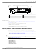


Table Of Contents
- Cisco CSS UCS Platform Series User Guide, CPS-UCS-1RU-K9 / CPS-UCS-2RU-K9
- Contents
- Preface
- Overview
- System Overview
- Status LEDs and Buttons
- Supported PSBU Hardware Configurations
- Server and Accessories Part Numbers
- Server Monitoring and Management Tools
- Supported Applications
- Supported Applications
- Installing the Server
- Replacing Hardware Components
- Preparing for Server Component Installation
- Installing or Replacing Server Components
- Server Specifications
- Related Documentation

4-15
Cisco CSS UCS Platform Series User Guide, CPS-UCS-1RU-K9 / CPS-UCS-2RU-K9
Chapter 4 Replacing Hardware Components
Installing or Replacing Server Components
Caution If you cannot safely view and access the component, remove the server from the rack.
c. Remove the top cover as described in the “Removing and Replacing the Server Top Cover” section
on page 4-3.
d. Remove any cables from the ports of the PCIe card that you are replacing.
Tip Label the cables when you disconnect them to aid correct connection to the new card.
e. Lift straight up on both ends of the PCIe riser to disengage it from the socket on the motherboard.
f. Pull evenly on both ends of the PCIe card to remove it from the socket on the PCIe riser.
If the riser has no card, remove the blanking panel from the rear opening of the riser.
Step 2 Install a new PCIe card:
a. Align the new PCIe card with the empty socket on the PCIe riser.
Note Align and insert the card’s rear panel tab into the riser’s rear panel opening at the same time you
align the card with the empty socket.
b. Push down evenly on both ends of the card until it is fully seated in the socket.
c. Ensure that the card rear panel tab sits flat against the PCIe riser rear panel opening.
d. Position the PCIe riser over its socket on the motherboard and over the alignment features (see
“Replacing the PCIe Riser”).
e. Carefully push down on both ends of the PCIe riser to fully engage its circuit board connector with
the socket on the motherboard.
f. Replace the top cover.
g. Replace the server in the rack, replace cables, and then power on the server by pressing the Power
button.
h. If the card that you replaced was a RAID controller, continue with “Restoring RAID Configuration
After Replacing a RAID Controller”.
Related Documentation
For more information, see “Replacing a PCIe Card” in the Cisco UCS C220 Server Installation and
Service Guide. Topics include:
• Special Considerations for Cisco UCS Virtual Interface Cards
• RAID Controller Card Cable Routing
• Installing Multiple PCIe Cards and Resolving Limited Resources
Installing or Replacing a PCIe Card: Cisco Connected Safety and Security UCS C240
For instructions to install or replace a PCIe card, see the following topics:
• PCIe Slots: Cisco Connected Safety and Security UCS C240, page 4-16