
Installation Guide


11-8
Cisco x90 Series Content Security Appliances Installation and Maintenance Guide
Chapter 11 Maintaining Cisco Content Security Appliances
Replacing Cisco Content Security Appliance Components
Warning
Hazardous voltage or energy may be present on DC power terminals. Always replace cover when
terminals are not in service. Be sure uninsulated conductors are not accessible when cover is in
place. Statement 1075
If you are using the Version 2 930W DC power supply, you connect power using a supplied 3-wire cable
with a keyed connector that plugs into a fixed power input socket on the power supply.
Warning
Before beginning this wiring procedure, turn off the DC power source from your facility’s circuit
breaker to avoid electric shock hazard.
Step 1 Turn off the DC power source from your facility’s circuit breaker to avoid electric shock hazard.
Step 2 Wire the supplied 3-wire connector cable to your facility’s DC power source. Attach the red wire to the
negative lead of your facility’s DC power source.
Note The supplied connector cable contains 8 AWG gauge wires. The recommended facility wire gauge is
8 AWG. The minimum facility wire gauge is 10 AWG.
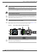
Step 3 Plug the supplied connector cable into the power input socket on the power supply. Figure 11-6 shows
that the connector is keyed to the socket so that the polarity is aligned correctly.
Figure 11-6 Version 2 930 W, –48 VDC Power Supply Connector Block
Step 4
Return power from your facility’s DC power source at the circuit breaker.
Step 5 Verify that power supply status LED is green.
1 Power supply status LED 3 Fixed power input socket
2 Power supply fault LED 4 Supplied connector cable
305170
930W DC
V2
1
2
43