
Installation Guide

10-7
Cisco x90 Series Content Security Appliances Installation and Maintenance Guide
Chapter 10 Cisco S690 Web Security Appliance
Summary of Features
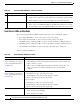
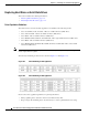
In Table 10-3, read the status and fault LED states together in each row to determine the event that cause
this combination.
Summary of Features
Table 10-4 lists a summary of appliance features.
.
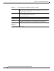
Data/Management port link status • Off—No link is present.
• Green—Link is active.
• Green, blinking—Traffic is present on the active link.
Unit Identification
• Off—The unit identification function is not in use.
• Blue—The unit identification function is activated.
Table 10-2 Rear Panel LEDs, Definitions of States (continued)
LED Name State
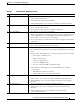
Table 10-3 Rear Power Supply LED States
Green PSU Status LED State Amber PSU Fault LED State Event
• Solid on • Off 12V main on (main power mode)
• Blinking • Off 12Vmain off (standby power mode)
• Off • Off No AC power input (all PSUs present)
• Off • On No AC power input (redundant supply active)
• Blinking • Solid on 12V over-voltage protection (OVP)
• Blinking • Solid on 12V under-voltage protection (UVP)
• Blinking • Solid on 12V over-current protection (OCP)
• Blinking • Solid on 12V short-circuit protection (SCP)
• Solid on • Solid on PSU fan fault/Lock (before OTP)
• Blinking • Solid on PSU fan fault/Lock (after OTP)
• Blinking • Solid on Over-temperature protection (OTP)
• Solid on • Blinking OTP warning
• Solid on • Blinking OCP warning
• Blinking • Off 12V main off (CR slave PSU is in sleep mode)
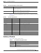
Table 10-4 Cisco S690 Web Security Appliance Features
Chassis Two rack-unit (2RU) chassis.
Processors Two E5–2680 v3 processor.
Memory Eight 8GB DDR4-2133 DIMM
1
.
Remote Power
Cycle
A Remote Power Cycle can be performed using a
1-Gb dedicated port.