
Installation Guide


10-4
Cisco x90 Series Content Security Appliances Installation and Maintenance Guide
Chapter 10 Cisco S690 Web Security Appliance
Using Status LEDs and Buttons for Maintenance
Using Status LEDs and Buttons for Maintenance
This section describes the location and meaning of LEDs and buttons and includes the following topics
• Front Panel LEDs, page 10-4
• Rear Panel LEDs and Buttons, page 10-6
Front Panel LEDs
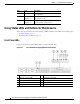
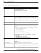
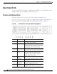
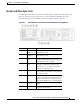
Figure 10-3 shows the front panel LEDs. Table 10-1 defines the LED states.
The model with 16 drives is shown.
Figure 10-3 Cisco S690 Web Security Appliance Front Panel LEDs
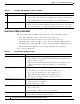
9 Data A 1-Gigabit Ethernet customer data interface.
10 Management
interface 3
A third Management Port. This 1-Gigabit
Ethernet interface cannot be used.
Item Port Description
1 Hard drive fault LED 6 Fan status LED
2 Hard drive activity LED 7 Temperature status LED
3 Power button/power status LED 8 Power supply status LED
4 Identification button/LED 9 Network link activity LED
5 System status LED