
Installation Guide


6-2
Cisco x90 Series Content Security Appliances Installation and Maintenance Guide
Chapter 6 Cisco M390 Content Security Management Appliance
Using Status LEDs and Buttons for Maintenance
Using Status LEDs and Buttons for Maintenance
This section describes the location and meaning of LEDs and buttons and includes the following topics
• Front Panel LEDs, page 6-2
• Rear Panel LEDs and Buttons, page 6-4
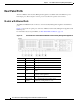
Front Panel LEDs
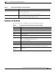
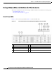
Figure 6-2 shows the front panel LEDs for the M390X model, with eight disk drives. Table 6-1 defines
the LED states.
Figure 6-2 Cisco M390 Content Security Management Appliance Front Panel LEDs
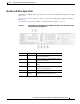
3 Data 3 A Gigabit Ethernet customer data interface.
4 Data 4 A Gigabit Ethernet customer data interface.
5 Remote
Power Cycle
The port that is used for Remote Power Cycle
(RPC).
6 Console The console port that directly connects a
computer to the appliance.
7 Data 5 A Gigabit Ethernet customer data interface.
8 Management
interface
The Gigabit Ethernet interface that is restricted
to management use only.
Item Port Description
1 Hard drive fault LED 6 Fan status LED
2 Hard drive activity LED 7 Temperature status LED
HDD 02 HDD 03
HDD 05 HDD 06 HDD 07 HDD 08
HDD 01
3 4
5 7 9
6 8
1 2
HDD 04