Cisco x90 Series Content Security Appliances Installation and Maintenance Guide April 7, 2016 Cisco Systems, Inc. www.cisco.com Cisco has more than 200 offices worldwide. Addresses, phone numbers, and fax numbers are listed on the Cisco website at www.cisco.com/go/offices.
THE SPECIFICATIONS AND INFORMATION REGARDING THE PRODUCTS IN THIS MANUAL ARE SUBJECT TO CHANGE WITHOUT NOTICE. ALL STATEMENTS, INFORMATION, AND RECOMMENDATIONS IN THIS MANUAL ARE BELIEVED TO BE ACCURATE BUT ARE PRESENTED WITHOUT WARRANTY OF ANY KIND, EXPRESS OR IMPLIED. USERS MUST TAKE FULL RESPONSIBILITY FOR THEIR APPLICATION OF ANY PRODUCTS.
CONTENTS About this Book CHAPTER 1 vii Installing Cisco x90 Series Content Security Appliances 1-1 Unpacking and Inspecting Cisco x90 Series Content Security Appliances Preparing for Cisco x90 Series Content Security Appliances Installation Installation Guidelines 1-3 Rack Requirements 1-4 Equipment Requirements 1-4 Slide Rail Adjustment Range 1-4 1-2 1-3 Installing Cisco x90 Series Content Security Appliances In a Rack 1-5 Using the Rack Kit to Install Cisco x90 Series Content Security Appliances
Contents CHAPTER 4 Cisco C690 Email Security Appliance Available Models 4-1 4-1 Rear Panel Ports 4-2 Models with Ethernet Ports 4-2 Models with Fiber Optic Ports 4-3 Using Status LEDs and Buttons for Maintenance Front Panel LEDs 4-4 Rear Panel LEDs and Buttons 4-6 Summary of Features CHAPTER 5 4-7 Cisco M190 Content Security Management Appliance Rear Panel Ports Summary of Features 6 Rear Panel Ports 5-5 6-1 Summary of Features 7 6-2 6-5 Cisco M690 Content Security Management Appliance Ava
Contents CHAPTER 8 Cisco S190 Web Security Appliance Rear Panel Ports 8-1 8-1 Using Status LEDs and Buttons for Maintenance Front Panel LEDs 8-2 Rear Panel LEDs and Buttons 8-4 Summary of Features CHAPTER 9 8-5 Cisco S390 Web Security Appliance Rear Panel Ports 9-1 9-1 Using Status LEDs and Buttons for Maintenance Front Panel LEDs 9-2 Rear Panel LEDs and Buttons 9-4 Summary of Features CHAPTER 10 9-2 9-5 Cisco S690 Web Security Appliance Available Models 8-2 10-1 10-1 Rear Panel Ports
Contents Remotely Resetting Appliance Power APPENDIX A Appliance Specifications Physical Specifications A-1 A-1 Environmental Specifications Power Specifications A-3 770 W AC Power Supply 650 W AC Power Supply APPENDIX B Power Cord Specifications 11-10 A-2 A-3 A-4 B-1 Supported Power Cords and Plugs B-1 AC Power Cord Illustrations B-3 Cisco x90 Series Content Security Appliances Installation and Maintenance Guide vi
About this Book This preface describes the audience, organization, and conventions of the Cisco x90 Series Content Security Appliances Installation and Maintenance Guide. It also provides information about how to obtain related documentation. Audience This guide is for experienced network administrators who configure and maintain Cisco Content Security Appliances. Conventions This document uses the following conventions for notes, cautions, and safety warnings.
Warning IMPORTANT SAFETY INSTRUCTIONS This warning symbol means danger. You are in a situation that could cause bodily injury. Before you work on any equipment, be aware of the hazards involved with electrical circuitry and be familiar with standard practices for preventing accidents. Use the statement number provided at the end of each warning to locate its translation in the translated safety warnings that accompanied this device.
Avvertenza IMPORTANTI ISTRUZIONI SULLA SICUREZZA Questo simbolo di avvertenza indica un pericolo. La situazione potrebbe causare infortuni alle persone. Prima di intervenire su qualsiasi apparecchiatura, occorre essere al corrente dei pericoli relativi ai circuiti elettrici e conoscere le procedure standard per la prevenzione di incidenti. Utilizzare il numero di istruzione presente alla fine di ciascuna avvertenza per individuare le traduzioni delle avvertenze riportate in questo documento.
Cisco x90 Series Content Security Appliances Installation and Maintenance Guide x
Aviso INSTRUÇÕES IMPORTANTES DE SEGURANÇA Este símbolo de aviso significa perigo. Você se encontra em uma situação em que há risco de lesões corporais. Antes de trabalhar com qualquer equipamento, esteja ciente dos riscos que envolvem os circuitos elétricos e familiarize-se com as práticas padrão de prevenção de acidentes. Use o número da declaração fornecido ao final de cada aviso para localizar sua tradução nos avisos de segurança traduzidos que acompanham o dispositivo.
Cisco x90 Series Content Security Appliances Installation and Maintenance Guide xii
Warning When installing the product, please use the provided or designated connection cables/power cables/AC adaptors. Using any other cables/adaptors could cause a malfunction or a fire. Electrical Appliance and Material Safety Law prohibits the use of UL-certified cables (that have the “UL” shown on the code) for any other electrical devices than products designated by CISCO.
Obtaining Documentation and Submitting a Service Request For information on obtaining documentation, using the Cisco Bug Search Tool (BST), submitting a service request, and gathering additional information, see What’s New in Cisco Product Documentation at: http://www.cisco.com/c/en/us/td/docs/general/whatsnew/whatsnew.html.
CH A P T E R 1 Installing Cisco x90 Series Content Security Appliances This chapter describes how to install Content Security Appliances, and it includes the following sections: Caution Warning • Unpacking and Inspecting Cisco x90 Series Content Security Appliances, page 1-2 • Preparing for Cisco x90 Series Content Security Appliances Installation, page 1-3 • Installing Cisco x90 Series Content Security Appliances In a Rack, page 1-5 Before you install, operate, or service an appliance, review th
Chapter 1 Installing Cisco x90 Series Content Security Appliances Unpacking and Inspecting Cisco x90 Series Content Security Appliances Unpacking and Inspecting Cisco x90 Series Content Security Appliances Caution When handling internal appliance components, wear an ESD strap and handle modules by the carrier edges only. Tip Keep the shipping container in case the appliance requires shipping in the future. Note The chassis is thoroughly inspected before shipment.
Chapter 1 Installing Cisco x90 Series Content Security Appliances Preparing for Cisco x90 Series Content Security Appliances Installation Preparing for Cisco x90 Series Content Security Appliances Installation This section provides information about preparing for installation, and it includes the following topics: • Installation Guidelines, page 1-3 • Rack Requirements, page 1-4 • Equipment Requirements, page 1-4 • Slide Rail Adjustment Range, page 1-4 Installation Guidelines Warning To prevent t
Chapter 1 Installing Cisco x90 Series Content Security Appliances Preparing for Cisco x90 Series Content Security Appliances Installation When you are installing an appliance, use the following guidelines: • Plan your site configuration and prepare the site before installing the appliance. See the Quick Start Guides for the Cisco x90 Series Content Security Appliances for the recommended site planning tasks.
Chapter 1 Installing Cisco x90 Series Content Security Appliances Installing Cisco x90 Series Content Security Appliances In a Rack Installing Cisco x90 Series Content Security Appliances In a Rack This section contains the following sections: • Using the Rack Kit to Install Cisco x90 Series Content Security Appliances, page 1-5 • Installing the Cable Management Arm (Optional), page 1-8 • Reversing the Cable Management Arm (Optional), page 1-9 Using the Rack Kit to Install Cisco x90 Series Content S
Chapter 1 Installing Cisco x90 Series Content Security Appliances Installing Cisco x90 Series Content Security Appliances In a Rack Attaching Inner Rail to Side of Two-RU Appliances 353365 Figure 1-2 1 1 Step 2 2 Front of appliance 2 Locking clip on inner rail Open the front securing plate on both slide-rail assemblies. The front end of the slide-rail assembly has a spring-loaded securing plate that must be open before you can insert the mounting pegs into the rack-post holes (see Figure 1-3).
Installing Cisco x90 Series Content Security Appliances Installing Cisco x90 Series Content Security Appliances In a Rack c. Press the securing plate release button, marked “PUSH.” The spring-loaded securing plate closes to lock the pegs in place. d. Adjust the slide-rail length, and then push the rear mounting pegs into the corresponding rear rack-post holes. The slide rail must be level front-to-rear. The rear mounting pegs enter the rear rack-post holes from the inside of the rack post.
Chapter 1 Installing Cisco x90 Series Content Security Appliances Installing Cisco x90 Series Content Security Appliances In a Rack Step 5 (Optional) Secure the appliance in the rack more permanently by using the two screws that are provided with the slide rails. Perform this step if you plan to move the rack with appliances installed.
Chapter 1 Installing Cisco x90 Series Content Security Appliances Installing Cisco x90 Series Content Security Appliances In a Rack Figure 1-6 Attaching the Cable Management Arm to the Rear of the Slide Rails 3 1 2 352584 4 1 CMA tab on arm farthest from the appliance and end of stationary outer slide rail 3 2 CMA tab on arm closest to the appliance and 4 end of inner slide rail attached to the appliance CMA tab on width-adjustment slider and end of stationary outer slide rail Rear of the appl
Chapter 1 Installing Cisco x90 Series Content Security Appliances Installing Cisco x90 Series Content Security Appliances In a Rack Figure 1-7 Reversing the CMA 352585 PUSH 2 1 CMA tab on end of width-adjustment slider 1 2 Cisco x90 Series Content Security Appliances Installation and Maintenance Guide 1-10 Metal button for rotating
CH A P T E R 2 Cisco C190 Email Security Appliance • Rear Panel Ports, page 2-1 • Using Status LEDs and Buttons for Maintenance, page 2-2 • Summary of Features, page 2-5 Rear Panel Ports Figure 2-1 shows the rear panel ports of the Cisco C190 Email Security Appliance. The model shown below has one power supply. It is also available with an optional second power supply.
Chapter 2 Cisco C190 Email Security Appliance Using Status LEDs and Buttons for Maintenance Using Status LEDs and Buttons for Maintenance This section describes the location and meaning of LEDs and buttons and includes the following topics • Front Panel LEDs, page 2-2 • Rear Panel LEDs and Buttons, page 2-4 Front Panel LEDs Figure 2-2 shows the front panel LEDs. Table 2-1 defines the LED states.
Chapter 2 Cisco C190 Email Security Appliance Using Status LEDs and Buttons for Maintenance Table 2-1 Front Panel LEDs, Definitions of States LED Name 1 2 3 4 5 Hard drive fault Hard drive activity Power button/LED Unit identification System status State • Off—The hard drive is operating properly. • Amber—Drive fault detected. • Amber, blinking—The device is rebuilding. • Amber, blinking with one-second interval—Drive locate function activated.
Chapter 2 Cisco C190 Email Security Appliance Using Status LEDs and Buttons for Maintenance Table 2-1 Front Panel LEDs, Definitions of States (continued) LED Name 8 9 State Power supply status Network link activity • Green—All power supplies are operating normally. • Amber, steady—One or more power supplies are in a degraded operational state. • Amber, blinking—One or more power supplies are in a critical fault state. • Off—The Ethernet link is idle.
Chapter 2 Cisco C190 Email Security Appliance Summary of Features Table 2-2 Rear Panel LEDs, Definitions of States (continued) LED Name State Data/Management port link status Rear unit identification • Off—No link is present. • Green—Link is active. • Green, blinking—Traffic is present on the active link. • Off—The unit identification LED is not in use. • Blue—The unit identification LED is activated. Summary of Features Table 2-3 lists the features of the C190 Email Security Appliance. .
Chapter 2 Summary of Features Cisco x90 Series Content Security Appliances Installation and Maintenance Guide 2-6 Cisco C190 Email Security Appliance
CH A P T E R 3 Cisco C390 Email Security Appliance • Rear Panel Ports, page 3-1 • Using Status LEDs and Buttons for Maintenance, page 3-2 • Summary of Features, page 3-5 Rear Panel Ports Figure 3-1 shows the rear panel features of the Cisco C390 Email Security Appliance. Figure 3-1 Cisco C390 Email Security Appliance Rear Panel Ports Item Port Description 1 Data 1 A Gigabit Ethernet customer data interface. 2 Data 2 A Gigabit Ethernet customer data interface.
Chapter 3 Cisco C390 Email Security Appliance Using Status LEDs and Buttons for Maintenance Using Status LEDs and Buttons for Maintenance This section describes the location and meaning of LEDs and buttons and includes the following topics • Front Panel LEDs, page 3-2 • Rear Panel LEDs and Buttons, page 3-4 Front Panel LEDs Figure 3-2 shows the front panel LEDs. Table 3-1 defines the LED states.
Chapter 3 Cisco C390 Email Security Appliance Using Status LEDs and Buttons for Maintenance Table 3-1 Front Panel LEDs, Definitions of States LED Name 1 2 3 4 5 Hard drive fault Hard drive activity Power button/LED Unit identification System status State • Off—The hard drive is operating properly. • Amber—Drive fault detected. • Amber, blinking—The device is rebuilding. • Amber, blinking with one-second interval—Drive locate function activated.
Chapter 3 Cisco C390 Email Security Appliance Using Status LEDs and Buttons for Maintenance Table 3-1 Front Panel LEDs, Definitions of States (continued) LED Name 8 9 State Power supply status Network link activity • Green—All power supplies are operating normally. • Amber, steady—One or more power supplies are in a degraded operational state. • Amber, blinking—One or more power supplies are in a critical fault state. • Off—The Ethernet link is idle.
Chapter 3 Cisco C390 Email Security Appliance Summary of Features Table 3-2 Rear Panel LEDs, Definitions of States (continued) LED Name State Rear unit identification • Off—The unit identification LED is not in use. • Blue—The unit identification LED is activated. Summary of Features Table 3-3 lists the features of the C390 Email Security Appliance. . Table 3-3 Cisco C390 Email Security Appliance Features Feature Description Chassis One rack-unit (1RU) chassis.
Chapter 3 Summary of Features Cisco x90 Series Content Security Appliances Installation and Maintenance Guide 3-6 Cisco C390 Email Security Appliance
CH A P T E R 4 Cisco C690 Email Security Appliance • Available Models, page 4-1 • Rear Panel Ports, page 4-2 • Using Status LEDs and Buttons for Maintenance, page 4-4 • Summary of Features, page 4-7 Available Models The Cisco C690 Email Security Appliance is available in the following models: Note • C690 - Has Ethernet data ports and four small form-factor (SFF) drives, with a 4-drive backplane. • C690X - Has Ethernet data ports and eight SFF drives, with 8-drive direct-connect backplane.
Chapter 4 Cisco C690 Email Security Appliance Rear Panel Ports Rear Panel Ports The Cisco C690 Email Security Appliance is available with either Ethernet ports or Fiber Optic ports, as described in separate sections below. Models with Ethernet Ports The C690 and C690X models of the Cisco Email Security Appliance have Ethernet ports. Figure 4-1 shows the rear panel ports of Cisco Email Security Appliances with Ethernet ports.
Chapter 4 Cisco C690 Email Security Appliance Rear Panel Ports Models with Fiber Optic Ports The C690-1G and C690-10G models of the Cisco Email Security Appliance have Fiber Optic ports. Figure 4-2 shows the rear panel ports of Cisco Email Security Appliances with Fiber Optic ports. For information about rear panel LEDs, see Rear Panel LEDs and Buttons, page 4-6.
Chapter 4 Cisco C690 Email Security Appliance Using Status LEDs and Buttons for Maintenance Using Status LEDs and Buttons for Maintenance This section describes the location and meaning of LEDs and buttons and includes the following topics • Front Panel LEDs, page 4-4 • Rear Panel LEDs and Buttons, page 4-6 Front Panel LEDs Figure 4-3 shows the front panel LEDs. Table 4-1 defines the LED states.
Chapter 4 Cisco C690 Email Security Appliance Using Status LEDs and Buttons for Maintenance Table 4-1 Front Panel LEDs, Definitions of States LED Name 1 2 3 4 5 Hard drive fault Hard drive activity Power button/LED Unit Identification System status State • Off—The hard drive is operating properly. • Amber—Drive fault detected. • Amber, blinking—The device is rebuilding. • Amber, blinking with one-second interval—Drive locate function activated.
Chapter 4 Cisco C690 Email Security Appliance Using Status LEDs and Buttons for Maintenance Table 4-1 Front Panel LEDs, Definitions of States (continued) LED Name 8 9 State Power supply status Network link activity • Green—All power supplies are operating normally. • Amber, steady—One or more power supplies are in a degraded operational state. • Amber, blinking—One or more power supplies are in a critical fault state. • Off—The Ethernet link is idle.
Chapter 4 Cisco C690 Email Security Appliance Summary of Features Table 4-2 Rear Panel LEDs, Definitions of States (continued) LED Name State Data/Management port link status Unit Identification • Off—No link is present. • Green—Link is active. • Green, blinking—Traffic is present on the active link. • Off—The unit identification function is not in use. • Blue—The unit identification function is activated.
Chapter 4 Cisco C690 Email Security Appliance Summary of Features Table 4-4 Cisco C690 Email Security Appliance Features (continued) Data Ports For model C690: Five 1-Gb BASE-T Ethernet LAN ports. For models C690-1G and C690-10G: Two 1Gb or 10-Gb fiber optic ports and one 1-Gb BASE-T Ethernet LAN port. Management I/O Supported connectors: • • One 1-Gb BASE-T Ethernet LAN ports One RS-232 serial port Power Two 650 W AC power supplies. Cooling Six fan modules for front-to-rear cooling.
CH A P T E R 5 Cisco M190 Content Security Management Appliance • Rear Panel Ports, page 5-1 • Using Status LEDs and Buttons for Maintenance, page 5-2 • Summary of Features, page 5-5 Rear Panel Ports Figure 5-1 shows the rear panel ports of the Cisco M190 Content Security Management Appliance. The model shown below has one power supply. It is also available with an optional second power supply.
Chapter 5 Cisco M190 Content Security Management Appliance Using Status LEDs and Buttons for Maintenance Using Status LEDs and Buttons for Maintenance This section describes the location and meaning of LEDs and buttons and includes the following topics • Front Panel LEDs, page 5-2 • Rear Panel LEDs and Buttons, page 5-4 Front Panel LEDs Figure 5-2 shows the front panel LEDs. Table 5-1 defines the LED states.
Chapter 5 Cisco M190 Content Security Management Appliance Using Status LEDs and Buttons for Maintenance Table 5-1 Front Panel LEDs, Definitions of States LED Name 1 2 3 4 5 Hard drive fault Hard drive activity Power button/LED Unit identification System status State • Off—The hard drive is operating properly. • Amber—Drive fault detected. • Amber, blinking—The device is rebuilding. • Amber, blinking with one-second interval—Drive locate function activated.
Chapter 5 Cisco M190 Content Security Management Appliance Using Status LEDs and Buttons for Maintenance Table 5-1 Front Panel LEDs, Definitions of States (continued) LED Name 8 9 State Power supply status Network link activity • Green—All power supplies are operating normally. • Amber, steady—One or more power supplies are in a degraded operational state. • Amber, blinking—One or more power supplies are in a critical fault state. • Off—The Ethernet link is idle.
Chapter 5 Cisco M190 Content Security Management Appliance Summary of Features Table 5-2 Rear Panel LEDs, Definitions of States (continued) LED Name State Data/Management port link status Rear unit identification • Off—No link is present. • Green—Link is active. • Green, blinking—Traffic is present on the active link. • Off—The unit identification LED is not in use. • Blue—The unit identification LED is activated.
Chapter 5 Summary of Features Cisco x90 Series Content Security Appliances Installation and Maintenance Guide 5-6 Cisco M190 Content Security Management Appliance
CH A P T E R 6 Cisco M390 Content Security Management Appliance • Available Models, page 6-1 • Rear Panel Ports, page 6-1 • Using Status LEDs and Buttons for Maintenance, page 6-2 • Summary of Features, page 6-5 Available Models The M390 SMA is available in the following models: • M390 - Has six 600 GB Hard Disk drives. • M390X - Has eight 600 GB Hard Disk drives. Rear Panel Ports Figure 6-1 shows the rear panel ports of the Cisco M390 Content Security Management Appliance.
Chapter 6 Cisco M390 Content Security Management Appliance Using Status LEDs and Buttons for Maintenance Item Port Description 3 Data 3 A Gigabit Ethernet customer data interface. 4 Data 4 A Gigabit Ethernet customer data interface. 5 Remote Power Cycle The port that is used for Remote Power Cycle (RPC). 6 Console The console port that directly connects a computer to the appliance. 7 Data 5 A Gigabit Ethernet customer data interface.
Chapter 6 Cisco M390 Content Security Management Appliance Using Status LEDs and Buttons for Maintenance Table 6-1 3 Power button/power status LED 8 Power supply status LED 4 Identification button/LED 9 Network link activity LED 5 System status LED Front Panel LEDs, Definitions of States LED Name 1 2 3 4 5 Hard drive fault Hard drive activity Power button/LED Unit identification System status State • Off—The hard drive is operating properly. • Amber—Drive fault detected.
Chapter 6 Cisco M390 Content Security Management Appliance Using Status LEDs and Buttons for Maintenance Table 6-1 Front Panel LEDs, Definitions of States (continued) LED Name 7 8 9 State Temperature status Power supply status Network link activity • Green—The appliance is operating at normal temperature. • Amber, steady—One or more temperature sensors breached the critical threshold. • Amber, blinking—One or more temperature sensors breached the non-recoverable threshold.
Chapter 6 Cisco M390 Content Security Management Appliance Summary of Features Table 6-2 Rear Panel LEDs, Definitions of States (continued) LED Name State Data/Management port link status Rear unit identification • Off—No link is present. • Green—Link is active. • Green, blinking—Traffic is present on the active link. • Off—The unit identification LED is not in use. • Blue—The unit identification LED is activated.
Chapter 6 Summary of Features Cisco x90 Series Content Security Appliances Installation and Maintenance Guide 6-6 Cisco M390 Content Security Management Appliance
CH A P T E R 7 Cisco M690 Content Security Management Appliance • Available Models, page 7-1 • Rear Panel Ports, page 7-2 • Using Status LEDs and Buttons for Maintenance, page 7-4 • Summary of Features, page 7-7 Available Models The Cisco M690 Content Security Management Appliance is available in the following models: Note • M690 - Has Ethernet data ports and ten small form-factor (SFF) drives, with a ten-drive backplane.
Chapter 7 Cisco M690 Content Security Management Appliance Rear Panel Ports Rear Panel Ports The Cisco M690 Content Security Management Appliance is available with either Ethernet ports or Fiber Optic ports. The description of these ports are described in separate sections below. Models with Ethernet Ports The M690 and M690X models of the Cisco Content Security Management Appliance have Ethernet ports.
Chapter 7 Cisco M690 Content Security Management Appliance Rear Panel Ports Models with Fiber Optic Ports The M690-1G and M690-10G models of the Cisco Content Security Management Appliance have Fiber Optic ports. Figure 7-2 shows the rear panel ports of Cisco Content Security Management Appliances with Fiber Optic ports. For information about rear panel LEDs, see Rear Panel LEDs and Buttons, page 7-6.
Chapter 7 Cisco M690 Content Security Management Appliance Using Status LEDs and Buttons for Maintenance Using Status LEDs and Buttons for Maintenance This section describes the location and meaning of LEDs and buttons and includes the following topics • Front Panel LEDs, page 7-4 • Rear Panel LEDs and Buttons, page 7-6 Front Panel LEDs Figure 7-3 shows the front panel LEDs. Table 7-1 defines the LED states.
Chapter 7 Cisco M690 Content Security Management Appliance Using Status LEDs and Buttons for Maintenance Table 7-1 Front Panel LEDs, Definitions of States LED Name 1 2 3 4 5 Hard drive fault Hard drive activity Power button/LED Unit Identification System status State • Off—The hard drive is operating properly. • Amber—Drive fault detected. • Amber, blinking—The device is rebuilding. • Amber, blinking with one-second interval—Drive locate function activated.
Chapter 7 Cisco M690 Content Security Management Appliance Using Status LEDs and Buttons for Maintenance Table 7-1 Front Panel LEDs, Definitions of States (continued) LED Name 8 9 State Power supply status Network link activity • Green—All power supplies are operating normally. • Amber, steady—One or more power supplies are in a degraded operational state. • Amber, blinking—One or more power supplies are in a critical fault state. • Off—The Ethernet link is idle.
Chapter 7 Cisco M690 Content Security Management Appliance Summary of Features Table 7-2 Rear Panel LEDs, Definitions of States (continued) LED Name State Data/Management port link status Unit Identification • Off—No link is present. • Green—Link is active. • Green, blinking—Traffic is present on the active link. • Off—The unit identification function is not in use. • Blue—The unit identification function is activated.
Chapter 7 Cisco M690 Content Security Management Appliance Summary of Features Table 7-4 Cisco M690 Content Security Management Appliance Features (continued) Data Ports For model M690: Five 1-Gb BASE-T Ethernet LAN ports. For models M690-1G and M690-10G: Two 1Gb or 10-Gb fiber optic ports and one 1-Gb BASE-T Ethernet LAN port. Management I/O Supported connectors: • • One 1-Gb BASE-T Ethernet LAN ports One RS-232 serial port Power Two 650 W AC power supplies.
CH A P T E R 8 Cisco S190 Web Security Appliance • Rear Panel Ports, page 8-1 • Using Status LEDs and Buttons for Maintenance, page 8-2 • Summary of Features, page 8-5 Rear Panel Ports Figure 8-1 shows the rear panel ports of the Cisco S190 Web Security Appliance. The model shown below has one power supply. It is also available with an optional second power supply.
Chapter 8 Cisco S190 Web Security Appliance Using Status LEDs and Buttons for Maintenance Item Port Description 6 Console Console port that directly connects a computer to the appliance. 7 Management interface 1 Gigabit Ethernet interface that is restricted to management use only. 8 Management interface 2 The secondary Management Port. This Gigabit Ethernet interface cannot be used.
Chapter 8 Cisco S190 Web Security Appliance Using Status LEDs and Buttons for Maintenance Table 8-1 Front Panel LEDs, Definitions of States LED Name 1 2 3 4 5 Hard drive fault Hard drive activity Power button/LED Unit identification System status State • Off—The hard drive is operating properly. • Amber—Drive fault detected. • Amber, blinking—The device is rebuilding. • Amber, blinking with one-second interval—Drive locate function activated.
Chapter 8 Cisco S190 Web Security Appliance Using Status LEDs and Buttons for Maintenance Table 8-1 Front Panel LEDs, Definitions of States (continued) LED Name 8 9 State Power supply status Network link activity • Green—All power supplies are operating normally. • Amber, steady—One or more power supplies are in a degraded operational state. • Amber, blinking—One or more power supplies are in a critical fault state. • Off—The Ethernet link is idle.
Chapter 8 Cisco S190 Web Security Appliance Summary of Features Table 8-2 Rear Panel LEDs, Definitions of States (continued) LED Name State Data/Management port link status Rear unit identification • Off—No link is present. • Green—Link is active. • Green, blinking—Traffic is present on the active link. • Off—The unit identification LED is not in use. • Blue—The unit identification LED is activated. Summary of Features Table 8-3 lists the features of the Cisco S190 Web Security Appliance.
Chapter 8 Summary of Features Cisco x90 Series Content Security Appliances Installation and Maintenance Guide 8-6 Cisco S190 Web Security Appliance
CH A P T E R 9 Cisco S390 Web Security Appliance • Rear Panel Ports, page 9-1 • Using Status LEDs and Buttons for Maintenance, page 9-2 • Summary of Features, page 9-5 Rear Panel Ports Figure 9-1 shows the rear panel ports of the Cisco S390 Web Security Appliance. Figure 9-1 Rear Panel Ports of Cisco S390 Web Security Appliances Item Port Description 1 Proxy port 1 Connect proxy port P1 to the network for both incoming and outgoing traffic.
Chapter 9 Cisco S390 Web Security Appliance Using Status LEDs and Buttons for Maintenance Item Port Description 6 Console Console port that directly connects a computer to the appliance. 7 Management interface 1 Gigabit Ethernet interface that is restricted to management use only. 8 Management interface 2 The secondary Management Port. This Gigabit Ethernet interface cannot be used.
Chapter 9 Cisco S390 Web Security Appliance Using Status LEDs and Buttons for Maintenance Table 9-1 Front Panel LEDs, Definitions of States LED Name 1 2 3 4 5 Hard drive fault Hard drive activity Power button/LED Unit identification System status State • Off—The hard drive is operating properly. • Amber—Drive fault detected. • Amber, blinking—The device is rebuilding. • Amber, blinking with one-second interval—Drive locate function activated.
Chapter 9 Cisco S390 Web Security Appliance Using Status LEDs and Buttons for Maintenance Table 9-1 Front Panel LEDs, Definitions of States (continued) LED Name 8 9 State Power supply status Network link activity • Green—All power supplies are operating normally. • Amber, steady—One or more power supplies are in a degraded operational state. • Amber, blinking—One or more power supplies are in a critical fault state. • Off—The Ethernet link is idle.
Chapter 9 Cisco S390 Web Security Appliance Summary of Features Summary of Features Table 9-3 lists the features of the S390 Web Security Appliance. . Table 9-3 Cisco S390 Web Security Appliance Features Feature Description Chassis One rack-unit (1RU) chassis. Processors One E5–2620 v3 processor. Memory Four 8GB DDR4-2133 DIMM1. Remote Power Control The Remote Power Control can be accessed through a 1-Gb dedicated port. Proxy Ports Two 1-Gb BASE-T Ethernet LAN ports.
Chapter 9 Summary of Features Cisco x90 Series Content Security Appliances Installation and Maintenance Guide 9-6 Cisco S390 Web Security Appliance
CH A P T E R 10 Cisco S690 Web Security Appliance • Available Models, page 10-1 • Rear Panel Ports, page 10-2 • Using Status LEDs and Buttons for Maintenance, page 10-4 • Summary of Features, page 10-7 Available Models The Cisco S690 Web Security Appliance is available in the following models: Note • S690 - Has Ethernet data ports and eight small form-factor (SFF) drives, with an eight-drive backplane.
Chapter 10 Cisco S690 Web Security Appliance Rear Panel Ports Rear Panel Ports The Cisco S690 Web Security Appliance is available with either Ethernet ports or Fiber Optic ports. The description of these ports are described in separate sections below. Models with Ethernet Ports The S690 and S690X models of the Cisco Web Security Appliance have Ethernet ports. Figure 10-1 shows the rear panel ports of the Cisco S690 Web Security Appliance with Ethernet ports.
Chapter 10 Cisco S690 Web Security Appliance Rear Panel Ports Models with Fiber Optic Ports The S690-1G and S690-10G models of the Cisco Web Security Appliance have Fiber Optic ports. Figure 10-2 shows the rear panel ports of Cisco Security Appliances with Fiber Optic ports. For information about rear panel LEDs, see Rear Panel LEDs and Buttons, page 10-6.
Chapter 10 Cisco S690 Web Security Appliance Using Status LEDs and Buttons for Maintenance Item Port Description 9 Data A 1-Gigabit Ethernet customer data interface. 10 Management interface 3 A third Management Port. This 1-Gigabit Ethernet interface cannot be used.
Chapter 10 Cisco S690 Web Security Appliance Using Status LEDs and Buttons for Maintenance Table 10-1 Front Panel LEDs, Definitions of States LED Name 1 2 3 4 5 Hard drive fault Hard drive activity Power button/LED Unit Identification System status State • Off—The hard drive is operating properly. • Amber—Drive fault detected. • Amber, blinking—The device is rebuilding. • Amber, blinking with one-second interval—Drive locate function activated.
Chapter 10 Cisco S690 Web Security Appliance Using Status LEDs and Buttons for Maintenance Table 10-1 Front Panel LEDs, Definitions of States (continued) LED Name 8 9 State Power supply status Network link activity • Green—All power supplies are operating normally. • Amber, steady—One or more power supplies are in a degraded operational state. • Amber, blinking—One or more power supplies are in a critical fault state. • Off—The Ethernet link is idle.
Chapter 10 Cisco S690 Web Security Appliance Summary of Features Table 10-2 Rear Panel LEDs, Definitions of States (continued) LED Name State Data/Management port link status Unit Identification • Off—No link is present. • Green—Link is active. • Green, blinking—Traffic is present on the active link. • Off—The unit identification function is not in use. • Blue—The unit identification function is activated.
Chapter 10 Cisco S690 Web Security Appliance Summary of Features Table 10-4 Cisco S690 Web Security Appliance Features (continued) Data Ports For model C690: Five 1-Gb BASE-T Ethernet LAN ports. For models C690-1G and C690-10G: Six 1Gb or 10-Gb fiber optic ports and one 1-Gb BASE-T Ethernet LAN port. Management I/O Supported connectors: • • One 1-Gb BASE-T Ethernet LAN ports One RS-232 serial port Power Two 650 W AC power supplies. Cooling Six fan modules for front-to-rear cooling.
CH A P T E R 11 Maintaining Cisco Content Security Appliances This chapter describes contains the following sections: • Monitoring System Health, page 11-1 • Preparing for Cisco Content Security Appliance Component Replacement, page 11-2 • Replacing Cisco Content Security Appliance Components, page 11-3 • Enabling Remote Power Cycling, page 11-9 • Remotely Resetting Appliance Power, page 11-10 Monitoring System Health Information about using SNMP to monitor system health is available in the user
Chapter 11 Maintaining Cisco Content Security Appliances Preparing for Cisco Content Security Appliance Component Replacement Preparing for Cisco Content Security Appliance Component Replacement This section includes the following topics: • Required Equipment, page 11-2 • Shutting Down and Powering Off the Appliance, page 11-2 • Serial Number Location, page 11-3 • Hot-Swap Replacement, page 11-3 Required Equipment The following equipment is used to perform the procedures in this chapter: • Numbe
Chapter 11 Maintaining Cisco Content Security Appliances Replacing Cisco Content Security Appliance Components Step 3 Disconnect the power cords from the power supplies in your appliance to completely power off the appliance. Serial Number Location The serial number (SN) for the appliance is printed on a label on the top of the appliance, near the front. Hot-Swap Replacement Some components can be removed and replaced without powering off and removing AC power from the appliance.
Chapter 11 Maintaining Cisco Content Security Appliances Replacing Cisco Content Security Appliance Components Replacing Hard Drives or Solid State Drives This section includes the following information: • Drive Population Guidelines, page 11-4 • Drive Replacement Procedure, page 11-5 Drive Population Guidelines The 90-Series Cisco Content Security Appliances are available in the following models: Note • Cisco C190, M190, S190, and C390 —Have two small form-factor (SFF) drives.
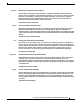
Chapter 11 Maintaining Cisco Content Security Appliances Replacing Cisco Content Security Appliance Components Drive Replacement Procedure Tip Step 1 Step 2 You do not have to shut down or power off the appliance to replace SAS hard drives because they are hot-swappable. Remove the drive that you are replacing or remove a blank drive tray from an empty bay: a. Press the release button on the face of the drive tray. See Figure 11-3. b.
Chapter 11 Maintaining Cisco Content Security Appliances Replacing Cisco Content Security Appliance Components Replacing Power Supplies The appliance can have one or two power supplies. When two power supplies are installed, they are redundant and hot-swappable, with one active power supply and one standby (1+1). This appliance also supports cold redundancy.
Chapter 11 Maintaining Cisco Content Security Appliances Replacing Cisco Content Security Appliance Components Figure 11-4 1 Power supply handle Figure 11-5 1 Replacing Power Supplies on 1RU Appliances 2 Power supply release lever Replacing Power Supplies on 2RU Appliances Power supply handle 2 Power supply release lever Installing a DC Power Supply The x690 models of Cisco Content Security Appliances are available with optional 930W DC power supplies.
Chapter 11 Maintaining Cisco Content Security Appliances Replacing Cisco Content Security Appliance Components Warning Hazardous voltage or energy may be present on DC power terminals. Always replace cover when terminals are not in service. Be sure uninsulated conductors are not accessible when cover is in place.
Chapter 11 Maintaining Cisco Content Security Appliances Enabling Remote Power Cycling Enabling Remote Power Cycling If you want to be able to remotely reset appliance power, you must enable and configure this functionality in advance, using the procedure described in this section. Before You Begin • Cable the dedicated Remote Power Cycle (RPC) port directly to a secure network. • Ensure that the appliance is accessible remotely; for example, open any necessary ports through the firewall.
Chapter 11 Maintaining Cisco Content Security Appliances Remotely Resetting Appliance Power Remotely Resetting Appliance Power If the appliance requires a hard reset, you can reboot the appliance chassis remotely using a third-party Intelligent Platform Management Interface (IPMI) tool. Restrictions • If you want be able to use this feature, you must enable it in advance, before you need to use it. For details, see Enabling Remote Power Cycling, page 11-9.
A P P E N D I X A Appliance Specifications This appendix includes the following sections and lists the technical specifications for the x90 Series Cisco Email Security Appliances (ESAs), Cisco Content Security Management Appliances (SMAs), and Cisco Web Security Appliances (WSAs): • Physical Specifications, page A-1 • Environmental Specifications, page A-2 • Power Specifications, page A-3 Physical Specifications Table A-1 lists the physical specifications for the following Cisco Content Security App
Appendix A Appliance Specifications Environmental Specifications Table A-2 lists the physical specifications for the following Cisco Content Security Appliances: • C690 Email Security Appliances • M690 Content Security Management Appliances • S690 Web Security Appliances Table A-2 Physical Specifications for Cisco Content Security Appliances with a 2 RU chassis Description Specification Height 3.4 in. (8.7 cm) Width 19.0 in. (48.26 cm) Depth 29.0 in. (73.
Appendix A Appliance Specifications Power Specifications Table A-3 Environmental Specifications Description Specification 37 Sound pressure level for x90 series Cisco Content Security Appliances with a 1 RU chassis. Measure A-weighted per ISO7779 LpAm (dBA) Operation at 73°F (23°C) 43 Sound pressure level for x90 series Cisco Content Security Appliances with a 2 RU chassis.
Appendix A Appliance Specifications Power Specifications 650 W AC Power Supply Table A-5 lists the specifications for each 650 W AC power supply (Cisco part number CCS-PWR-ACV2-650W) used in the x90 series Cisco Content Security Appliances with a 2 RU chassis.
A P P E N D I X B Power Cord Specifications This appendix provides supported power cable specifications. Supported Power Cords and Plugs Each power supply has a separate power cord. Standard power cords or jumper power cords are available for connection to the appliance. The jumper power cords, for use in racks, are available as an optional alternative to the standard power cords. Note Only the approved power cords or jumper power cords provided with the appliance are supported.
Appendix B Power Cord Specifications Supported Power Cords and Plugs Table B-1 Supported Power Cords for the Appliance (continued) Length Description Feet Meters Power Cord Reference Illustration CAB-9K10A-IT Power Cord, 250 VAC 10 A CEI 23-16 Plug Italy 8.2 2.5 Figure B-7 CAB-9K10A-SW Power Cord, 250 VAC 10 A MP232 Plug Switzerland 8.2 2.5 Figure B-8 CAB-9K10A-UK Power Cord, 250 VAC 10 A BS1363 Plug (13 A fuse) United Kingdom 8.2 2.
Appendix B Power Cord Specifications Supported Power Cords and Plugs AC Power Cord Illustrations This section includes the AC power cord illustrations. See Figure B-1 through Figure B-15. Figure B-1 SFS-250V-10A-AR 2500 mm Cordset rating: 10 A, 250/500 V MAX Length: 8.2 ft Plug: EL 219 (IRAM 2073) Figure B-2 186571 Connector: EL 701 (IEC60320/C13) CAB-9K10A-AU Connector: EL 701C (IEC 60320/C15) Plug: EL 206 A.S.
Appendix B Power Cord Specifications Supported Power Cords and Plugs CAB-9K10A-EU Plug: M2511 Cordset rating: 10A/16 A, 250 V Length: 8 ft 2 in. (2.
Power Cord Specifications Supported Power Cords and Plugs Figure B-7 CAB-9K10A-IT Cordset rating: 10 A, 250 V Length: 8 ft 2 in. (2.5 m) Connector C15M (EN60320/C15 ) 186575 Plug: I/3G (CEI 23-16) Figure B-8 CAB-9K10A-SW Cordset rating: 10 A, 250 V Length: 8 ft. 2 in (2.
Appendix B Power Cord Specifications Supported Power Cords and Plugs Figure B-10 CAB-AC-250V/13A Connector: EL 701 (IEC60320/C13) Plug: EL312MoldedTwistlock (NEMA L6-20) CAB-N5K6A-NA Plug: NEMA 6-15P Cordset rating: 10 A, 250 V Length: 8.2 ft Connector: IEC60320/C13 Figure B-12 186570 Figure B-11 186568 Cordset rating 13A, 250V (6.
Power Cord Specifications Supported Power Cords and Plugs Figure B-13 CAB-C13-CBN, Jumper Power Cord (0.68 m) Connector: HS10S Plug: SS10A Figure B-14 186569 Cordset rating 10A, 250V (686mm) CAB-C13-C14-2M, Jumper Power Cord (2 m) Connector: HS10S Plug: SS10A Figure B-15 336014 Cordset rating 10A, 250V (2.0 m) CAB-C13-C14-AC, Jumper Power Cord (3 m) Cordset rating 10A, 250V (3.
Appendix B Supported Power Cords and Plugs Cisco x90 Series Content Security Appliances Installation and Maintenance Guide B-8 Power Cord Specifications