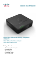
Quick Start Guide Cisco SPA100 Series Analog Telephone Adapters SPA112 Two Port Phone Adapter SPA122 ATA with Router Package Contents • Analog Telephone Adapter • Ethernet Cable • Power Adapter • Quick Start Guide • Product CD-ROM
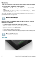
Welcome Thank you for choosing a Cisco SPA100 Series Analog Telephone Adapter. This product family includes the following models: • SPA112 Two-Port Phone Adapter: 2 FXS ports and 1 10/100 WAN port. • SPA122 ATA with Router: 2 FXS ports, 1 10/100 WAN port, 1 10/100 LAN port, and built-in router. This guide describes how to physically install the equipment and how to get started with the configuration.
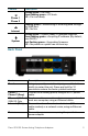
Feature Phone 1 Phone 2 Internet System Description Steady green—On hook. Slow flashing green—Off hook. Off—Port not ready. Flashing green—Transmitting or receiving data through the WAN port. Off—No link. Steady green—System ready, IP address acquired. Slow flashing green—Acquiring IP address. (By default, uses DHCP.) Fast flashing green—Upgrading firmware. Off—No power or system can not boot up.
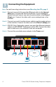
3 Connecting the Equipment NOTE For wall-mounting instructions, see Mounting the ATA, page 9. STEP 1 Connect one end of the provided Ethernet cable to the Internet (Blue) port. Connect the other end directly to your broadband network deviceConnect one end of a phone cable to the Phone 1 (Gray) port. Connect the other end to your analog phone or fax machine. STEP 2 Connect one end of another phone cable to another analog phone or fax machine. Connect the other end to the Phone 2 (Gray) port.
Configuration and Management of the ATA 4 You can use the web-based configuration utility to set up your ATA. You also can use the built-in Interactive Voice Response (IVR) system. Using the Web-Based Configuration Utility STEP 1 Connect your computer to the same subnet as the ATA. For example, if the ATA is connected to a LAN port on your router, also connect your computer to a LAN port on your router. Note: On SPA122, you can connect your computer to the ETHERNET (Yellow) port of the ATA.
Using the IVR for Administration An IVR system is available to help you to configure and manage your ATA. You can use the telephone keypad to select options and to make your entries. To access the IVR menu: STEP 1 Connect an analog phone to the Phone port of the ATA. STEP 2 Press the star key four times: **** STEP 3 After the greeting plays, press the keys on the phone keypad to select your options. STEP 4 Enter the code for the desired action. See the IVR Actions table for details.
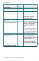
IVR Actions IVR Action Menu Option Enter IVR Menu **** Check Internet Connection 100 Type Set Internet Connection Type 101 Choices and Instructions DHCP: 0 Static IP: 1 PPPoE: Press 2 PPPoE, DHCP: Press 3 DHCP, PPPoE: Press 4 Check Internet IP Address (WAN port) Set Static IP Address (WAN) 110 111 Enter the IP address by using numbers on the telephone key pad. Use the * (star) key when entering a decimal point.
IVR Action Set Gateway IP Address Menu Option 131 Choices and Instructions To enter the value, press numbers on the telephone key pad. Press the * (star) key to enter a decimal point. Note: This option is available only after you choose Static IP as the Internet Connection Type, through option 101. Check MAC Address 140 Check Firmware Version 150 Check Primary DNS Server Setting Set Primary DNS Server 160 161 To enter the value, press numbers on the telephone key pad.
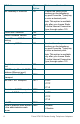
IVR Action Factory Reset of Unit Menu Option 73738 WARNING: All non-default RESET settings will be lost. This includes network and service provider data. Reboot of Voice System 732668 REBOOT User Factory Reset of Unit 877778 WARNING: All userchangeable non-default settings will be lost. This may include network and service provider data. 5 Choices and Instructions When prompted, press 1 to confirm, or press * (star) to cancel. After you hear “Option successful,” hang up the phone. The ATA reboots.
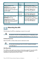
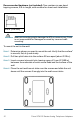
Recommended hardware (not included): Two number-six pan-head tapping screws, 5/8-in. length, with anchors for sheet rock installation. 5/8 in. (15.8 mm) WARNING Insecure mounting might damage the ATA or cause injury. Cisco is not responsible for damages incurred by insecure wallmounting. To mount the unit to the wall: STEP 1 Determine where you want to mount the unit. Verify that the surface is smooth, flat, dry, and sturdy. STEP 2 Drill two pilot holes into the surface 58 mm apart (about 2.28 in.).
6 Where to Go From Here Support Cisco Small Business Support Community www.cisco.com/go/smallbizsupport Cisco Small Business Support and Resources www.cisco.com/go/smallbizhelp Phone Support Contacts www.cisco.com/go/sbsc Cisco Small Business Firmware Downloads www.cisco.com/go/software Cisco Small Business Open Source Requests www.cisco.com/go/smallbiz_opensource_ request Product Documentation Cisco Small Business Analog Telephone Adapters www.cisco.
Americas Headquarters Cisco Systems, Inc. 170 West Tasman Drive San Jose, CA 95134-1706 USA www.cisco.com Small Business Support, Global: www.cisco.com/go/sbsc 78-19933-01 Cisco and the Cisco Logo are trademarks of Cisco Systems, Inc. and/or its affiliates in the U.S. and other countries. A listing of Cisco's trademarks can be found at www.cisco.com/go/ trademarks. Third party trademarks mentioned are the property of their respective owners.