4035993 Rev A Cisco RF Gateway 1 Remote Provisioning Utility (RPU) User Guide
For Your Safety Explanation of Warning and Caution Icons Avoid personal injury and product damage! Do not proceed beyond any symbol until you fully understand the indicated conditions. The following warning and caution icons alert you to important information about the safe operation of this product: You may find this symbol in the document that accompanies this product. This symbol indicates important operating or maintenance instructions. You may find this symbol affixed to the product.
Notices Trademark Acknowledgments Cisco, Cisco Systems, the Cisco logo, and the Cisco Systems logo are registered trademarks or trademarks of Cisco Systems, Inc. and/or its affiliates in the U.S. and certain other countries. All other trademarks mentioned in this document are the property of their respective owners. Publication Disclaimer Cisco Systems, Inc. assumes no responsibility for errors or omissions that may appear in this publication.
Contents Safe Operation for Software Controlling Optical Transmission Equipment v Chapter 1 Introduction 1 Features and Benefits .............................................................................................................. 3 Primary Benefits.......................................................................................................... 3 Chapter 2 Provisioning 5 Before you Begin ................................................................................................
Contents Help Menu ................................................................................................................. 36 Chapter 4 Customer Support Information 37 Obtaining Product Support .................................................................................................. 38 Support Telephone Numbers..................................................................................
Safe Operation for Software Controlling Optical Transmission Equipment Safe Operation for Software Controlling Optical Transmission Equipment If this manual discusses software, the software described is used to monitor and/or control ours and other vendors’ electrical and optical equipment designed to transmit video, voice, or data signals. Certain safety precautions must be observed when operating equipment of this nature.
1 Chapter 1 Introduction Overview The Cisco RF Gateway 1 Remote Provisioning Utility (RPU) is a Windows-based tool designed to simplify initial provisioning of multiple RF Gateway 1 units in an operator's system. Purpose This user guide provides the necessary information to install, operate, maintain, and upgrade the RPU application. Who Should Use This Document This document is intended for authorized service personnel who have experience working with the RF Gateway 1 or similar equipment.
In This Chapter 2 Features and Benefits .............................................................................
Features and Benefits Features and Benefits Primary Benefits The RPU provides the following benefits: 4035993 Rev A Enables mass initial provisioning of RF Gateway 1 databases in SDV deployments. Provisioning of 48 and 96 channel RFGW1 hardware configurations is supported. Enables mass upgrade provisioning of RFGW1 databases from 48 channels to 96 channels. Enables bulk provisioning of run-time port and channel control settings.
2 Chapter 2 Provisioning This chapter describes the components for provisioning the RPU. In This Chapter 4035993 Rev A Before you Begin ..................................................................................... 6 Provisioning Overview ..........................................................................
Chapter 2 Provisioning Before you Begin Before you begin, make sure to check the following: 6 Your server is running Windows. You have the RPU distribution CD or have downloaded the RPU installer. You can connect to the Cisco product server.
Provisioning Overview Provisioning Overview The RPU merges a common reference database with unique parameters such as IP address, Transport Stream Identifier (TSID), and frequency information from a SDV Design File to generate and distribute configuration files for each RFGW1. These operations can also be performed on a per QAM basis by accessing the embedded web user interface of the RFGW1. The RFGW1 provisioning parameters are stored internally in a .xml database format.
Chapter 2 Provisioning SDV Design File SDV Design Files are commonly used by SDV customers to maintain an accounting of configuration parameters and service group associations for the various devices in the network. The SDV Design File was originally conceived to capture legacy SDV Server/GQAM networks in a single common file that could be shared between Cisco network engineering and customers. The SDV Design File now supports USRM and RFGW1.
Provisioning Overview 2nd Generation SDV Design File The following sections describe the five tabs of the SDV Design File. Hub_Info Sheet The following screen shows the Hub_Info sheet. RFGW1 QAMS and System Spreadsheet The QAMS and System spreadsheet corresponds to the QAMS and System tabs on the RFGW1 GUI. These tabs are included in the SDV Design File as a common location to facilitate communication and discussion regarding an operator's preferences for the settings in the Reference Database.
Chapter 2 Provisioning QAMS Spreadsheet 10 4035993 Rev A
Provisioning Overview System Spreadsheet Device_Info Spreadsheet The Device_Info spreadsheet is the primary configuration used for RPU data.
Chapter 2 Provisioning The following screen shows the Device_Info spreadsheet. The RPU data is divided into two major sections: Identification and IP Configuration Port and Channel Frequency and TSID Configuration The following parameters are included in Identification and IP Configuration: Headend - Name of the Headend the RFGW1 is configured with on the network. Hub - Name of the installation location.
Provisioning Overview Note: The RPU will not create databases or configure GQAM type devices. GQAM configuration data will be used in the Data Integrity Tests, and the GQAM data will be displayed in the RPU data display dialogs. Max QAM - Identifies the number of QAM channels for the entire device. 48 or 96 are the supported values. The following parameters are included in Port and Channel Frequency and TSID Configuration: SG ID - Service Group ID to which this port is assigned.
Chapter 2 Provisioning SG_Info Sheet The SG_Info Sheet is used to configure SDB Service Group information. The following parameters must be configured for use by the RPU: SGID SG Name Primary SDV Server The other parameters are used for other system configuration purposes. The RPU requires that any service group listed on the Device_Info sheet be defined in the SG_Info sheet. The following screen shows the SG_Info sheet.
3 Chapter 3 Installation and General Operation This chapter describes how to install and operate the RPU. In This Chapter 4035993 Rev A Installing the RPU................................................................................. 16 Initial Provisioning Mode.................................................................... 19 Creating Databases and Programming the RFGW1 ........................ 24 RFGW1 Bulk Provisioning ..................................................................
Chapter 3 Installation and General Operation Installing the RPU Uninstalling Previous RPU Older versions of the Cisco RPU must be uninstalled before installing a new version. Follow the instructions below to uninstall an older version RPU. 1 On the windows menu, navigate to Start > Control Panel. 2 Double-click Add or Remove Programs. Result: The program window is displayed. 3 Highlight the Cisco RFGW Remote Provisioning Utility and click Remove.
Installing the RPU The following screen is displayed. 3 Click the Computer button to start the installation. Result: The following screen is displayed. 4 4035993 Rev A Click Continue.
Chapter 3 Installation and General Operation Result: The following screen is displayed (depending upon your computer's configuration). 5 Click Yes. Result: The following screen is displayed. 18 6 Click OK. 7 Result: Installation is completed.
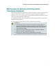
Initial Provisioning Mode Initial Provisioning Mode The RPU can perform initial provisioning for both 48 and 96 channel RFGW1 models. The RPU uses the MAX QAM column of the Device_Info tab of the SDV Design File to determine whether the RFGW1 is intended to be provisioned with 48 or 96 channels of data. Importing Provisioning Parameters Before starting the provisioning procedure, you must import the Reference Database and the SDV Design File.
Chapter 3 Installation and General Operation Creating Reference Database (Phase 1 Step 1b) Reference databases must be created in order to capture all desired provisioning parameters that not included in the SDV Design File spreadsheet. The RPU maintains separate reference databases for 48 and 96 channel RFGW1 models. The user must identify an appropriate RFGW1 to be used as the reference for each model. Follow the instructions below for creating the reference database.
Initial Provisioning Mode Result: The reference database is ready for collection to the RPU repository. 9 If necessary, repeat for all RFGW1 units. Importing Reference Database (Phase 1 Step 1c) Follow the instructions below to import the reference database. There are two options (Copy Local File or Ftp File From RFGW) to choose from when importing. The FTP option is Cisco recommended. 1 From the Import Method drop-down window, select Ftp File From RFGW.
Chapter 3 Installation and General Operation Importing SDV Design File Spreadsheet (Phase 1 Step 1d) Follow the instructions below to import the SDV Design File spreadsheet. 1 Click Locate Excel Spreadsheet. Result: A standard Windows Open dialog menu is displayed. 2 From the Windows menu, browse to the spreadsheet to import. 3 On the RPU screen, click Import Data. Result: The RPU extracts all the required data from the spreadsheet and displays the Hub names in the Hub List dialog box.
Initial Provisioning Mode Note: The user can double-click the log report to create a text log file. The RPU automatically displays the created log file in the default text editor.
Chapter 3 Installation and General Operation Creating Databases and Programming the RFGW1 After the provisioning data has been imported, the user is ready to create databases and program the RFGW1 devices. Verifying SDV Design File Spreadsheet Configuration Data (Phase 2 Step 2a) This step allows the user to manually verify configuration data imported from the SDV Design File spreadsheet. Make sure to check all imported data for each unit.
Creating Databases and Programming the RFGW1 3 Once the data has been verified as accurate, click Data OK. Creating RFGW1 Configuration Database (Phase 2 Step 2b) Follow the instructions below to create the configuration database(s). 1 From the Select HUB window, select the desired HUB to configure. Result: All units configured for this HUB are displayed in the Select RFGW dialog box. 2 Highlight the unit(s) for which you want to create a configuration database.
Chapter 3 Installation and General Operation Programming the RFGW1 with Configuration Database (Phase 2 Step 2c) Follow the instructions below to program RFGW1s with the Configuration databases. Note: There are two options for programming a list of RFGW1s. These options are configured using the Configure menu. 1 Select RFGW Reboot Options and Limits. The following options are available: Asynchronous - Programs each RFGW1 and does not wait for the unit to reboot.
Creating Databases and Programming the RFGW1 3 From the Select RFGW window, highlight the unit(s) to be programmed. Note: To program more than one unit, hold down the key and click an additional list element, or hold down the key to select a range of units. 4 Click Ping Selected. 5 Result: The RPU pings each unit selected and displays results in the status log window. If an RFGW does not respond to the ping, it will not be able to be programmed. 6 Click Check SW Version.
Chapter 3 Installation and General Operation Result: All RFGW1s configured for this Hub are displayed. 2 Select a single unit to verify. Result: The selected RFGW1 configuration is displayed. 3 Choose from the following five optional verification techniques. – Manual Verify. Displays the RFGW1 in a browser and uses the GUI interface to compare configuration data displayed for the selected RFGW1.
Creating Databases and Programming the RFGW1 – 4 Auto Verify. Created DB against in-Memory DB. This process determines if the in memory RFGW1 settings have been modified since the RPU created the RFGW1 database. Click Auto Verify. Result: Status is displayed in window. 5 If all verification tests passed, click Verify OK. Result: The RFGW status display shows the RFGW1 as verified.
Chapter 3 Installation and General Operation RFGW1 Bulk Provisioning The RPU provides a bulk provisioning feature to configure specific settings on one or more RFGW1s. This provisioning is accomplished via SNMP and does not require the system to reboot. Set Port Power/Port Control Levels (Step 3a) This feature provides a mechanism to bulk provision one or more of the RFGWs RF port power/port control levels. Follow the instructions below. 1 From the Hub List, select desired Hub.
RFGW1 Bulk Provisioning Result: The status log displays the results of all SNMP set commands. Set Combined Channels (Phase 3 Step 3b) This feature allows the user to bulk provision one or more RFGWs RF port combined channels. 1 From the Hub List, select desired Hub. Result: All units configured for this Hub are displayed. 2 From the Select RFGW box, select the unit for which you would like to set combined channels.
Chapter 3 Installation and General Operation Set Channel Mute This feature allows the user to bulk provision one or more of the RF Gateways port channel mute setting. 1 From the Hub List window, select desired Hub. Result: All units configured for this Hub are displayed. 2 From the Select RFGW window, select the unit for which you would like to set channel mute.
RPU Menu Options RPU Menu Options This section describes the RPU menu options. File Menu The File Menu allows the user to import and export database files. File > Import > Import - Copy DB files File > Export > Export - Copy DB Files File > Exit View Menu The View menu allows the user to perform the following tasks. 4035993 Rev A View > Excel Workbook. Opens the workbook configured in the "Import Excel Workbook" path in Step 1.c in Microsoft Excel. View > Selected RFGW in Browser.
Chapter 3 Installation and General Operation Configure Menu The Configure Menu allows the user to configure the following. 34 RFGW1 FTP Account Information - The RPU must have the FTP account information to log onto the RFGW1. RFGW1 Reboot Options and Limits - The RPU must reboot the RFGW1 to get the new database files created by the RPU to become the active database files. The following parameters configure the actions and timeouts for reboot.
RPU Menu Options – Wait After Reboot Done (sec). Number of seconds to wait after the RFGW1 reboots before continuing with processing. The RPU uses a ping command to determine if the RFGW1 rebooted. This extra wait time after the ping has responded allows other RFGW1 services to become operational. Reference SW Version Match Override - The RPU compares the software versions of the RFGW1 being programmed and the reference RFGW1.
Chapter 3 Installation and General Operation Help Menu The Help Menu allows the user to view the following tasks. 36 Help > Manual. Displays the RPU manual document. Help > About. Displays the About dialog that contains the RPU version information.
4 Chapter 4 Customer Support Information Introduction This chapter contains information on obtaining product support. Obtaining Product Support IF… THEN… you have general questions about this product contact your distributor or sales agent for product information or refer to product data sheets on www.cisco.com. you have technical questions about this product call the nearest Technical Support center. you have customer service questions call the nearest Customer Service about this product center.
Chapter 4 Customer Support Information Obtaining Product Support IF… THEN… you have general questions about this product contact your distributor or sales agent for product information or refer to product data sheets on www.cisco.com. you have technical questions about this product call the nearest Technical Service center or Cisco office. you have customer service questions or need a return material authorization (RMA) number call the nearest Customer Service center or Cisco office.
Obtaining Product Support Region Centers Telephone and Fax Numbers Mexico, Central America, Caribbean Mexico For Technical Support, call: Telephone: 52-3515152599 Fax: 52-3515152599 For Customer Service, call: Telephone: 52-55-50-81-8425 Fax: 52-55-52-61-0893 Email: sa-latam-cs@cisco.
Glossary E ECM Entitlement Control Messages. ECMG Entitlement Control Message Generator. EIS Event Information Scheduler EMM Entitlement Management Messages ES Elementary Stream. F FTP file transfer protocol. Allows users to transfer text and binary files to and from a personal computer, list directories on the foreign host, delete and rename files on the foreign host, and perform wildcard transfers between hosts. G GQAM GUI graphical user interface.
Glossary I IP Internet protocol. A standard that was originally developed by the United States Department of Defense to support the internetworking of dissimilar computers across a network. IP is perhaps the most important of the protocols on which the Internet is based. It is the standard that describes software that keeps track of the internetwork addresses for different nodes, routes, and outgoing/incoming messages on a network. Some examples of IP applications include email, chat, and Web browsers.
Glossary RU rack unit. RU is the measuring unit of vertical space in a standard equipment rack. One RU equals 1.75" (44.5 mm). S SCG Scrambling Control Group. SCS Simulcrypt Synchronizer.
Index B Before you Begin • 6 C Configure Menu • 34 Configure RPU Repository Location (Phase 1 Step 1a) • 19 Creating Databases and Programming the RFGW1 • 24 Creating Reference Database (Phase 1 Step 1b) • 20 Creating RFGW1 Configuration Database (Phase 2 Step 2b) • 25 customer support information • 37 Customer Support Information • 37 E ECM • 41 ECMG • 41 EIS • 41 EMM • 41 ES • 41 Importing SDV Design File Spreadsheet (Phase 1 Step 1d) • 22 Initial Provisioning Mode • 19 Installation and General Operati
Index Set Port Power/Port Control Levels (Step 3a) • 30 Support Telephone Numbers • 38 V Verifying RFGW Programming Data (Phase 2 Step 2d) • 27 Verifying SDV Design File Spreadsheet Configuration Data (Phase 2 Step 2a) • 24 View Menu • 33 46 4035993 Rev A
5030 Sugarloaf Parkway, Box 465447 Lawrenceville, GA 30042 678.277.1000 This document includes various trademarks of Cisco Systems, Inc. Please see the Notices section of this document for a list of Cisco Systems, Inc., trademarks used in this document. Product and service availability are subject to change without notice. © 2010 Cisco Systems, Inc. All rights reserved.