
Troubleshooting Guide

Release the forced protection switch.•
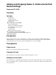
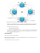
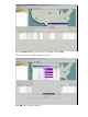
This is the UPSR ring topology in the lab setup as seen from the CTC network view:
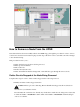
Check Circuit Integrity
Complete the steps in the instructions provided in order to check the circuit integrity:
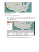
From the CTC network view confirm all circuits are in an Active state.
If any circuits are in an Incomplete state then do not continue. Refer to the Best Practices When
Configuring Circuits on the ONS 15454 document in order to resolve issues with circuits in an
Incomplete state.
1.
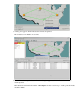
Confirm all circuits are in an Active state before you conitnue.2.
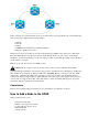
Initiate a Forced Protection Switch
Complete these instructions in order to initiate a forced protection switch:
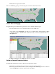
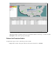
Manually force traffic from the span where the new node (Node4) is inserted.1.
A forced protection switch can cause a service disruption if the UPSR ring is not free from errors.
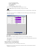
Check the PM Stats for all of the optical cards in the UPSR:
2.