
Troubleshooting Guide
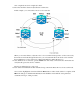

Once completed, Node4 is completely isolated.
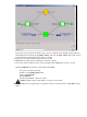
Reconnect the fibers between adjacent Node1 and Node3.
In this example, you connect Slot 5 Node1 to slot 13 Node3.
When you reconnect fibers to adjacent nodes, it is a recommended best practice to first connect only
the Tx fibers and check the light levels before you connect the Rx fibers. Rx levels can be found in
the Card Reference section of the Cisco ONS 15454 Reference Guide, Release 3.4.
13.
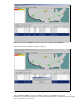
Once all fibers are reconnected, open the Alarms tab of the newly connected Node3 and Node4 and
verify that the span cards are free of alarms.
Resolve any alarms before you proceed.
14.
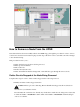
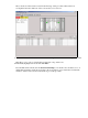
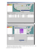
Now delete and rebuild the circuits identified in step 4. From the Network view, locate each circuit.
One at a time, highlight the circuit and click the Delete button. After circuit deletion is complete, click
OK in the dialog box. Click the Create button and rebuild the circuit with the same parameters
documented in step 4 of this procedure.
15.