
Troubleshooting Guide
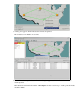
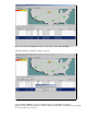
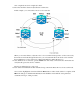

In the previous screenshot from the lab setup, you can see that the circuit actually changes STS and
VT through Node4. It enters through STS2, VT1−1, and exits via STS3, VT2−1. This circuit needs to
be deleted and recreated at the last step in this procedure.
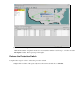
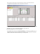
Repeat step 6 for all circuits that appear in the node view.7.
Manually force traffic away from all spans connected to Node4.8.
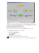
A forced protection switch can cause service disruption if the UPSR ring is not free of errors.
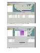
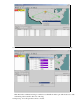
Check the PM Stats for all of the optical cards in the UPSR:
Log into each shelf in the ring.♦
Click on each UPSR optical card.♦
Choose Performance.♦
Click Refresh.♦
Verify that all fields contain zero values.♦
Caution: Traffic is unprotected during a forced protection switch.
9.
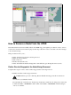
From the Network view, right−click on a span that connects to Node4 and choose Circuits from the
menu.
10.