Adding and Dropping Nodes in Unidirectional Path Switched Rings Document ID: 18480 Contents Introduction Prerequisites Requirements Components Used Background Information Conventions How to Add a Node to the UPSR Check Circuit Integrity Initiate a Forced Protection Switch Connect Fibers to the New Node Re−launch CTC Update Circuits Release the Protection Switch How to Remove a Node From the UPSR Delete Circuits Dropped at the Node Being Removed Related Information Introduction This document describes how
In this document, it is assumed that the new node is racked and powered up with all of its cards installed and their provisioning completed. Provisioning includes: • General • Network • Timing • SONET Data Communications Channels (SDCCs) • Place the optical ports in service References for the previous tasks can be found in the Setting Up a UPSR section of the Cisco ONS 15454 Procedure Guide, Release 3.4. Be sure to run test traffic through the new node in order to verify that all hardware is operational.
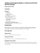
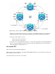
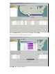
• Release the forced protection switch. This is the UPSR ring topology in the lab setup as seen from the CTC network view: Check Circuit Integrity Complete the steps in the instructions provided in order to check the circuit integrity: 1. From the CTC network view confirm all circuits are in an Active state. If any circuits are in an Incomplete state then do not continue.
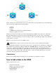
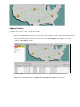
a. Log into each shelf in the ring. b. Click on each UPSR optical card. c. Choose Performance. d. Click Refresh. e. Verify that all fields contain zero values. If you see zero values in all fields, then the span runs free of errors. Caution: Traffic is unprotected during a forced protection switch. 3. From the Network view locate the span where the new node is to be inserted, Node1 to Node3 in the lab setup. Right−click on the span and choose Circuits from the menu.
2. Ensure that you have an East to West configuration around the ring. Note: It is a recommended best practice to consider the optical trunk card furthest to the right in the shelf as the East fiber, and the optical trunk card furthest to the left in the shelf as the West fiber.
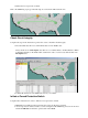
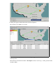
Update Circuits Complete these steps in order to update the circuits: 1. Click on the Circuits tab and wait a few minutes for the circuits to finish loading, that includes spans. Once the circuits finish loading, notice that some are in an Incomplete state. Make a note of the number of Incomplete circuits. 2. All Incomplete circuits need to be updated in order to account for the added new Node4. Right−click on Node4 and choose Update Circuits With New Node from the menu.
3. A dialog box appears, which indicates that circuits are updated. The circuits become Active one at a time. 4. When all circuits are updated, a confirmation dialog box appears, which indicates the number of circuits updated. This number should match the number of Incomplete circuits noted in step 1. At this point all circuits should be Active.
5. Click OK in the dialog box. Note: If the number of updated circuits does not match the number noted in step 1, or if there are still Incomplete circuits, then repeat steps 2 through 5. Release the Protection Switch Complete these steps in order to release the protection switch: 1. Right−click on either of the spans adjacent to the new Node4 and choose Circuits.
2. From the UPSR Switch drop−down menu, choose Clear and then Apply. Click Yes when the confirmation dialog box appears. 3. Click OK in the information dialog box.
How to Remove a Node From the UPSR Now that Node4 has been successfully added to the UPSR ring, go through the procedures in order to remove it. Add some circuits for demonstration purposes that drop at Node4 in order to start with some minor changes to the current lab setup: This procedure involves you to: • Delete circuits dropped at the node being removed. • Initiate protection switches. • Remove the node. • Re−fiber the adjacent nodes.
2. Click on the circuit to highlight it in order to delete these circuits, then click Delete. Click Yes when the confirmation dialog box appears. 3. Click OK when the informational dialog box appears. Press the Ctrl or Shift key in order for multiple circuits to be highlighted for deletion. 4. Identify and document the parameters for any circuits that change STS or VT while they pass through the node (Node4) to be removed.
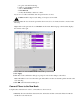
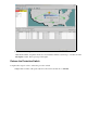
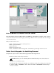
These circuits are deleted and recreated in the final step of this procedure. This task is best accomplished from the shelf view of the node (Node4) to be removed. 5. At the Shelf view, click Circuits and ensure that the Scope is set to Node from the drop down menu. This allows you to only see circuits that pass through or drop at this node. 6. Individually highlight each circuit and click Edit. From the Edit window make sure the Show Detailed Map box is checked.
In the previous screenshot from the lab setup, you can see that the circuit actually changes STS and VT through Node4. It enters through STS2, VT1−1, and exits via STS3, VT2−1. This circuit needs to be deleted and recreated at the last step in this procedure. 7. Repeat step 6 for all circuits that appear in the node view. 8. Manually force traffic away from all spans connected to Node4. 9. A forced protection switch can cause service disruption if the UPSR ring is not free of errors.
11. From the UPSR Switch Selector, choose Force from the drop−down menu and then click Apply. Click Yes in the confirmation dialog box. This forces all traffic from the span, which causes it to take an alternate path around the other side of the ring. 12. Repeat step 11 for all spans that connect to Node4.
Once completed, Node4 is completely isolated. 13. Reconnect the fibers between adjacent Node1 and Node3. In this example, you connect Slot 5 Node1 to slot 13 Node3. When you reconnect fibers to adjacent nodes, it is a recommended best practice to first connect only the Tx fibers and check the light levels before you connect the Rx fibers. Rx levels can be found in the Card Reference section of the Cisco ONS 15454 Reference Guide, Release 3.4. 14.
Related Information • Best Practices When Configuring Circuits on the ONS 15454 • Technical Support & Documentation − Cisco Systems Contacts & Feedback | Help | Site Map © 2014 − 2015 Cisco Systems, Inc. All rights reserved. Terms & Conditions | Privacy Statement | Cookie Policy | Trademarks of Cisco Systems, Inc.