
Manual

Cisco Packet Data Serving Node (PDSN) Release 2.0
Redundancy and Load Balancing
45
12.3(11)T
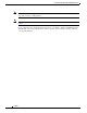
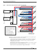
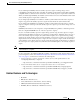
Figure 8 PDSN Controller -Member Architecture for MWAM on the Catalyst 6500
PDSNs that are designated as controllers, perform member PDSN selection and load balancing. The
following list describes the major functions of the controllers:
• Controllers maintain the load information for all members—they obtain the load information by
seeking the cluster members. Alternatively, the members send the load value at configurable
intervals inside a session origination or termination message. Controllers synchronize by
exchanging information as needed.
• The link on which controllers exchange information is an HSRP-based state information exchange
(HA redundancy is based on this type of implementation).
• The link on which the active controller and members exchange information is a unicast HSRP
address for the active controller, but must be configured on the members.
MWAM card
1.1.1.1
1.1.3.1
1.2.3.1
1.2.4.1
1.1.4.1
1.1.1.1
1.1.3.1
1.2.3.1
1.2.4.1
1.1.4.1
MWAM card
1.1.2.1
1.1.5.1
1.2.5.1
1.2.6.1
1.1.6.1
1.1.2.1
1.1.5.1
1.2.5.1
1.2.6.1
1.1.6.1
MWAM card
1.2.1.1
1.1.7.1
1.2.7.1
1.2.8.1
1.1.8.1
1.2.1.1
1.1.7.1
1.2.7.1
1.2.8.1
1.1.8.1
MWAM card
1.2.2.1
1.1.9.1
1.2.9.1
1.2.10.1
1.1.10.1
1.2.2.1
1.1.9.1
1.2.9.1
1.2.10.1
1.1.10.1
MWAM card
1.2.1.1
1.1.7.1
1.2.7.1
1.2.8.1
1.1.8.1
Active Standby Controller’s part of HSRP group
Access-port/line card
MWAM card
One 6500 Chassis with Four MWAM cards
Two VLAN’s, one for
the RED cluster and the
other for Blue Cluster
84368
Active Standby Controller’s part of HSRP group
Legend:
Two clusters are denoted by Red & Blue
Dark shades are Controllers, and lighter
shades are Members
Dashed lines represent logical
connections (configured VLANs)
Solid lines represent external physical
connections to the IP cloud
PCF 1
PCF 2
PCF n
PDSN addr configured:
1.1.1.1,
1.1.2.1
PCF-PDSN SAs
configured for: 1.1.1.1,
1.1.2.1, 1.1.3.1, 1.1.4.1,
... 1.1.n.1 or global
BSC,
PCF
BSC,
PCF
BSC,
PCF