
Manual


Cisco Packet Data Serving Node (PDSN) Release 2.0
System Overview
3
12.3(11)T
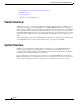
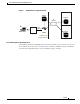
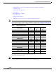
Figure 1 The CDMA Network
As the illustration shows, the mobile station, which must support either Simple IP or Mobile IP, connects
to a radio tower and BTS. The BTS connects to a BSC, which contains a component called the Packet
Control Function (PCF). The PCF communicates with the Cisco PDSN through an A10/A11 interface.
The A10 interface is for user data and the A11 interface is for control messages. This interface is also
known as the RAN-to-PDSN (R-P) interface. For the Cisco PDSN Release 2.0, you must use a Fast
Ethernet (FE) interface as the R-P interface on the 7200 platform, and a Giga Ethernet (GE) interface on
the MWAM platform.
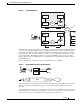
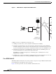
Figure 2 illustrates the communication between the RAN and the Cisco PDSN.
Figure 2 RAN-to-PDSN Connection: the R-P Interface
The IP networking between the PDSN and external data networks is through the PDSN-to-intranet/Internet
(P
i
) interface. For the Cisco PDSN Release 2.0, you can use either an FE or GE interface as the P
i
interface.
For “back office” connectivity, such as connections to a AAA server, or to a RADIUS server, the interface is
media independent. Any of the interfaces supported on the Cisco 7206 can be used to connect to these types
of services; however, Cisco recommends that you use either an FE or GE interface.
PDSNRAN
Visited Access Provider Network
M
obile station
BTS
BSC
PCF
IP
Network
IP
Network
Visited
AAA
Home
IS
P
riv
Hom
e
Se
rv
Hom
e A
PDSNRAN
Subscribed Access Provider Network
BTS
BSC
PCF
IP
Network
R-P Interface
AAA
R-P Interface
RAN
BTS
BSC
PCF
R-P Interface
PDSN
Mobile station
PPP GRE PPP IP
42688
IP